By John M. Prousalidis
Marine Engineering Laboratory, Naval Architecture and Marine Engineering Department, National Technical University of Athens, Greece
Emerging Applications of Transient Analysis: Electric Transportation
PSCAD® and other transient simulation applications have historically been used by energy utilities for system planning and power quality applications. However, there are many other emerging applications for transient simulation. With the trend toward the use of electric and hybrid-electric vehicles, electric ships, and the expansion of rapid transit systems based on electric power, power system simulation programs will need to adapt to specifically address these mini power systems.
Electric Ships
The electric power grid of a ship can be regarded as a small scale, autonomous, industrial type compact power system. A ship's electric energy system consists of a generator set and a distribution cabling system serving the loads. In the case of an AC conventional ship power system, there are at least two main AC generators driven by diesel engines, gas turbines or the main propulsion engine. Electric power is supplied often via substations to all electric loads consisting of:
1. The conventional auxiliary systems (lighting, motors driving rotating machinery), similar to an industrial plant.
2. The main and auxiliary ship propulsion systems.
Typical ship electrical networks can operate at 50/60 Hz while warship applications often require 400 Hz systems. Increased electric power demands in ships have led to the introduction of medium ("high" in ship installations) voltage operating levels of 3.3 and 6 kV. The ship grounding system is usually of the unearthed type.

Figure 1. The "All Electric Ship"
Recent developments in power semiconductor and power electronics technology and their application in drive and control systems have enabled Integrated Full Electric Propulsion (IFEP) of ships. The term "Electric Ship" now generally refers to a ship with a full electric propulsion system. The advent of AC electric propulsion in ships has introduced a whole new set of complexities on shipboard:
1. The main propulsion system comprises at least one huge power motor driving the ship propeller. New electric motor types (permanent magnet synchronous motors, advanced induction motors, multi-phase motors of radial, axial or transverse flux motors) have been constructed in an attempt to achieve higher efficiency and reliability indices. The propulsion motors are fed by power converters, which are responsible for the ship speed control in conjunction with their associated controllers. Speed control is achieved mainly either by vector flux control or direct torque control.
2. The auxiliary propulsion system (also called Dynamic Positioning System, DPS) consisting of side propellers, the bow and stern thrusters, assisting the ship maneuvers. The DPS is usually driven by AC induction motors supplied via PWM (Pulse Width Modulated) controllers.
3. According to the AES (All Electric Ship) concept, every major or minor system onboard the ship, propulsion being the predominant one, will eventually be electrified and served by a rather large scale electric system (of several tens of MW) with multiple redundancies in components and circuits.
The Requirement for Simulation
The emergence of electric propulsion in ships has made accurate simulation and modeling a must. Transient simulation analysis is used to perform studies involving the modeling of electromagnetic and other switching transients on ship electric energy systems comprising both AC and DC subsystems.
The systems that require modeling are the same as in any modern power system. The systems contain a high degree of power electronic switching components and require an understanding of the impact of all system modules on the operation of the ship electric system.
The broad areas of study include propulsion, switching transients, and power quality investigations.
Propulsion: main or auxiliary propulsion motor start-up and steady-state operation in conjunction with their power electronic converters (cyclo-converters, synchro-converters and PWM inverters).
Switching transients: overvoltages and overcurrents due to making or breaking circuit breakers (e.g. transformer electrification, cable disconnection, fault clearances, load shedding etc.)
Power quality: investigation of power quality problems introduced by the extensive use of power electronics in propulsion drives, pulsed loads (e.g. weaponry in warships) and navigation instruments (e.g. radar). The harmonic distortion in both current and voltage waveforms provokes increased reactive losses but also EMI problems.
The requirement for power system simulation is a necessity on such a critical self-contained entity as a ship. The same tools that have played a role in the optimization of our electrical utility grids will play a significant role in research and deployment of advanced ship electrical and propulsion systems.
PSCAD Case studies
Motor start-up. Starting-up of PWM driven cargo pumps
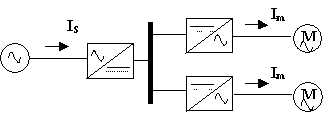
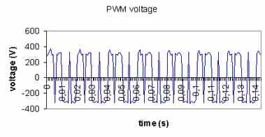
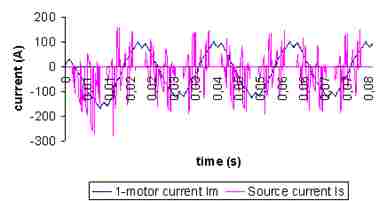
Two cargo pumps start working simultaneously. The pump motors are supplied by their PWM inverters which in turn are fed by a common DC-bus where the AC voltage is rectified (see Figure 2). In Figure 3, the voltage output of the PWM inverter is presented while in Figure 4, the inrush current of one motor (not considerably distorted) is shown in comparison with the AC source total current supplying the pair of pumps (highly distorted).

Figure 2. Schematic of the twin cargo pump system

Figure 3. PWM line voltage output driving cargo pump motor

Figures 4. Inrush current during pump-motor starting-up Starting-up of cyclo-converter driven synchronous motor
In Figure 5, the medium voltage output of a cyclo-converter supplying the main propulsion synchronous motor of a ship is depicted, while in Figure 6 the corresponding inrush current during motor starting-up is shown. It is highlighted that the synchronous motor initially starts as an induction motor via its auxiliary cage winding, while few cycles later its field winding is activated and the motor is synchronized.

Figure 5. Cyclo-converter line voltage output driving cargo pump motor

Figure 6. Inrush current cyclo-converter line voltage output driving cargo pump motor
Short-line fault in marine type cable
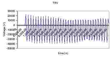
The consequences of clearing a short-line single-phase fault (approximately 200 m away from the circuit breaker) are shown in the voltage waveform of the faulted phase-to-clear (Figure 7). It is worth noting that in marine type cable, resistive component is of equal if not of greater value than the inductive reactance (~0.2 Ohm/km), while the capacitive conductance is of significant value, too (~8000 Ohm-1 /km).

Figure 7. Transient Recovery Voltage (TRV) developed during clearance of single-phase fault nearby a 10 kV circuit breaker