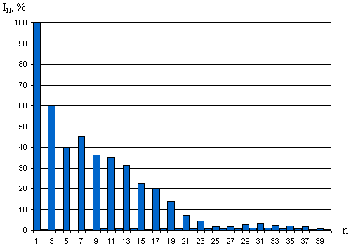
Figure 1 - The spectrum of harmonic components of the current of CFL Maxus 32w

Up to 80-s years of XX century as the major electrical loads were linear loads such as induction motors, incandescent lamps, resistance furnace, etc. In connection with scientific and technical progress in the field of electrical engineering appeared new electric load, powered performed using a variety of thyristor converters and nonlinear elements. The curves of current of these loads are very different from the sinusoidal shape, which affects the parameters of electric power supply, power quality and working conditions of other electric loads.
In recent years, an ever-increasing use of non-linear (pulse) load, which include PCs, TVs, copiers, uninterruptible power supply units (UPS), gas-discharge lamps, thyristor controllers, air conditioners, microwave ovens and many others. Due to the nonlinearity of the loadings their power spectrum contains higher harmonics, which leads to dangerous phenomena in the network. Higher harmonics can lead to the following consequences:
The same situation is observed in networks of lighting. Nowadays gradual replacement of incandescent lamps (IL) for compact fluorescent lamps (CFL) taking place as well as designing new lighting systems using CFLs and fluorescent lamps (FL).
All the CFLs, in contrast to LL, include electronic ballasts. Their curve of current differs from the current sine wave much more than that of FLs. First of all it is a consequence of the small size of the CFL’s ballast, as well as reducing the cost of CFL due to absence of elements that approximate the curve of current to the sinusoidal form.
Given all the above facts, there is the question of the proper and accurate calculation of today's power networks of illumination, given the wide variety of loads. The correct calculation will exclude the development of emergency situations, will allow defining the power quality and applying measures to prevent it possible reduction.
As time-current characteristics of the CFLs and FLs differ from IL and is not included in the modern normative documents, the challenge is to examine and develop recommendations for the calculation of electric lighting networks with the use of these kinds of lamps. To do this in my work is used the so-called "common" method of calculation of electrical networks. The generality of the method is in its universality: it can be calculated all kinds of loads, because the calculation is carried out on the instantaneous values of voltage and current. This method allows the accurate calculation of the resulting network settings, find the instantaneous values of the necessary quantities, graphically represent the results of calculations.
There is computational complexity in finding the values of integrals of the current function, especially, the values of their derivatives because of the sharply alternating current consumption of CFLs. To eliminate this shortcoming in the work used spline functions, which describe the shape of the curves of current and voltage, measured at discrete points. Spline functions allow finding the values of integrals and derivatives with a high degree of accuracy at any time.
As the CFLs are being increasingly used as direct replacement for the IL and being one of the most non-linear lighting load further research and calculations were made on the example of electrical network of illumination using CFLs.
In my work I studied 14 CFLs of different power and manufacturers, there were calculated parameters, made the analysis and comparison of the characteristics of these lamps. There was modeled and calculated electrical network using one kind of CFLs as the example of using the general method of calculating the electrical networks of illumination.
By modeling the network of illumination on the example of lecture-room № 8.411, replacing 18 incandescent lamps of 150 watts with CFLs Maxus 32watts (6 lamps per phase) were obtained curves of the current in the wires of four-phase network, the curves of voltage drops in them, and the resulting curves of phase and line voltage of network.
1. The components of current and power of CFLs.
The curves of currents of CFLs, in contrast to the ILs, have a wide spectrum of harmonic components. For the CFL Maxus 32w the spectrum of harmonics is shown in Fig. 1
Figure 1 - The spectrum of harmonic components of the current of CFL Maxus 32w
Because of this, except the active and reactive power consumption there is also being consumed extra power, called the power of distortion. This is part of reactive power, which characterizes the processes caused by the interaction between different harmonics of voltage and current.
Full power lamp can be calculated by the next formula:

Calculating parameters of CFL Maxus 32w following results were obtained:
P = 27,5 W - Active power (all harmonics);
Q = -8,59 var - reactive power (all harmonics).
S`= 28,8 VA - total power output without distortion;
D = 33,7 var - power of distortion;
S = 44,3 VA - full power of CFL.
The results show that power of distortion is a big part of the total power consumption of the CFL. The power of distortion doesn’t do any useful work but loads electrical network. Table 1 shows the currents' values of the CFL.
Table 1 - Values of components of the current of CFL Maxus 32w
| Maxus 32w | IP, А | IQ, А | IS`, А | ID, А | IS, А |
| 0,12 | -0,037 | 0,126 | 0,147 | 0,193 |
In contrast to the CFLs, ILs consume from the electrical network only active power (provided that voltage is sinusoidal). For comparison, we calculated approximately equal to luminous flux of CFL (32 W) incandescent lamp with (150 W) (Table 2).
Table 2 - Values of components of the current of IL 150 W
| IL 150 W | IP, А | IQ, А | IS`, А | ID, А | IS, А |
| 0,652 | 0 | 0 | 0 | 0,652 |
2. The flow of current in neutral wire in the equal allocation of lamps over the phases.
Simulated uniform load over the phases (6 CFLs per one phase), were obtained curves of the currents in the phases and the neutral wire (Fig. 2)

Figure 2 - Curves of the currents flowing in phases and the neutral
The appearance of current in neutral wire with equally distributed load over the phases caused due to the presence of higher harmonics that are multiples of three. Since the curve of current of CFL is periodic, the values of even harmonics can be assumed to be zero and in the neutral wire will flow amount of currents of odd harmonics of multiples of three (3rd, 9 th, 15 th, etc.).
The RMS value of current in neutral conductor exceeds the value of current of the phase conductors in 1,5 times (Table 3). For comparison the results of the simplified calculation of the same network, but with the use of incandescent lamps on the assumption that the voltage curve is sine (Table 4).
Table 3 - Values of currents and power using CFLs Maxus 32W
| IRMS, A | Imax, A | P, W | Q, var | S`, VA | D, var | S, VA | |
| Phase A | 1,16 | 4,37 | 165 | -51,6 | 173 | 202 | 266 |
| Phase B | 1,16 | 4,37 | 165 | -51,6 | 173 | 202 | 266 |
| Phase C | 1,16 | 4,37 | 165 | -51,6 | 173 | 202 | 266 |
| Neutral | 1,74 | 3,81 | 0 | 0 | 0 | 398 | 398 |
Table 4 - Values of currents and power using ILs 150 W
| IRMS, А | Imax, А |
P, W |
Q, var | S`, VA | D, var | S, VA | |
| Phase A | 3,9 | 5,53 | 900 | 0 | 900 | 0 | 900 |
| Phase B | 3,9 | 5,53 | 900 | 0 | 900 | 0 | 900 |
| Phase C | 3,9 | 5,53 | 900 | 0 | 900 | 0 | 900 |
| Neutral | 0 | 0 | 0 | 0 | 0 | 0 | 0 |
According to the Ukrainian Regulations for Electrical Equipment Setup (Section 1.3.8), the neutral conductor should have the conductivity of not less than 50% of the conduction of phase conductors and, if it is necessary, can be increased to 100%. In our case, even an equal cross-section of phase and neutral conductor will cause an overload of the latter, and this happens when load allots symmetrically to the phases. The current value in the neutral wire will be even greater if the lamps are not equally allocated to phases. This indicates that today’s regulations and designing standards are unacceptable for modern electrical networks.
3. Significant voltage drop in the reactance of electrical network.
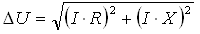
Voltage drop is composed of the voltage drop in the resistance and reactance of electrical network, and for the linear load is calculated by the formula:
where I – RMS current, A;
R – resistance of the wire, Ohm;
X – reactance of the wire at nominal frequency of alternating current, Ohm.
For the nonlinear load voltage drop in the reactance depends on the current frequency, in other words, the number of harmonic components. The higher the harmonic number, the greater the reactance of an electrical network. Reactance for harmonic component of current is calculated as:

 - Angular frequency, s-1;
Considering the harmonic spectrum of current of CFL (Fig. 1) and the dependence of the reactance of wire on the number of harmonics there was calculated voltage drop in the phase, the neutral wire and the loop phase-zero. For all the wires the values of R and X were raised 0.63 ohms and 0.3 ohms respectively. Figure 3 shows the curves of voltage drops in the phase, the neutral conductor and the loop phase-zero, in Fig. 4 - the curve of phase voltage, taking into account the drop of voltage in the loop phase-zero, and in Fig. 5 – curves of phase and line voltage taking into account the drop of voltage in phase wires.
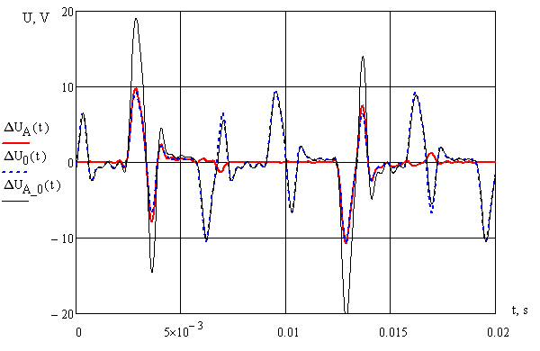
Figure 3 - Curves of voltage drops in the phase, the neutral conductor and the loop phase-zero
Table 5 - Values of voltage drop by using CFLs
 UR, V UR, V |
UX, V |
URMS, V |
Umax, V |
|
| PhaseA | 0,73 | 2,31 | 2,45 | 10,7 |
| Phase B | 0,73 | 2,31 | 2,45 | 10,7 |
| Phase C | 0,73 | 2,31 | 2,45 | 10,7 |
| Neutral | 1,09 | 3,76 | 3,91 | 10,43 |
| Phase-neutral | 1,59 | 5,37 | 5,6 | 21,1 |
As seen from Table. 5, the bulk of the voltage drop (about 90%) takes place in the reactance of electrical network.
Knowing the curve of the voltage drop in the loop phase-zero, there was obtained the curve of phase voltage of electrical network supplying the lighting load, assuming that without load the curve of phase voltage is sinusoidal (Fig. 4)

Figure 4 - The curve of phase voltage, taking into account losses in the loop phase-zero
Also, there were calculated curves of the phase voltages, taking into account voltage drops only in phase conductors (for a three-wire network) and calculated line voltages to assess its quality (Fig. 5).
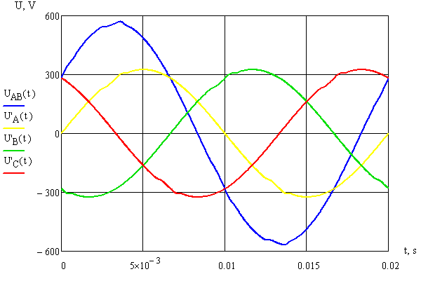
Figure 5 - Curves of phase and line voltages, taking into account the drops of voltage in phase wires.
The calculation results show that the line voltages are distorted much lesser than phase voltages in the four-phase network, as there are no losses in the neutral wire. For the four-phase network losses in the neutral wire (with the same resistance of the wires) are higher than in the phase wire due to the flowing the sum of higher harmonic multiples of three in neutral from all of three phases.
Applying the calculation of loads by current curves there is become more obvious effects occurring in electrical networks with modern loads. General method of calculation makes it possible to accurately calculate the instantaneous values of all major electrical parameters at any time, to visualize the results of calculations. As a result of the calculation of total load curves there can be determined all power quality parameters, which determines the State Standard 13109-97, as well
as international standards, as this method provides a universal data for further processing.
It becomes clear from the results of the calculation of loads that the use of the existing rules relating the cross-section of a neutral conductor, is unacceptable. According to calculations, in the electrical network of illumination with uniform nonlinear load (CFLs) over the phases minimum cross-section of neutral conductor when feeding a large number of nonlinear loads should be no less than 150% of the cross-section of phase wires.
Sharply variable current of CFLs leads to the same abrupt changes in instantaneous values of voltage. Using high power nonlinear loads there can be observed a significant distortion of sinusoidal voltage, which affects the electromagnetic compatibility of other electrical devices in the network and can lead to premature failure of electrical equipment.
At the time of writing the Abstract master's work is not completed yet. The final results of the study can be taken from me or my supervisor after December 2010.