Valve engine - electromechanical system, which consists of a synchronous machine and inverter frequency (IF), in which the phase inverter switch in the function of the rotor position.
In the absence of a mechanical collector synchronous motor with permanent magnets (PMSM) has significant advantages over the direct current motor:
• lack of sites that require maintenance;
• ensuring explosion;
• large overload capacity for torque;
• fast response, the possibility of optimizing the operating modes for speed and load;
• highest energy indicators;
• high reliability and overactive resource work;
• low motor overheating when working in the modes of possible congestion.
Thus, the benefits of PMSM with electronic control systems combine the best features of contactless motors and d.c. motors, and often surpass them.
In connection with these advantages PMSM increasingly replacing d.c. motors from their traditional areas of use. Now based PMSM tracking actuator
supply verstatov with numerical program control, and industrial robots, electric household appliances (tape recorders, fans of computer power supplies, disk drives, etc.)
of low and very low power [7].
Motivation
PMSM with sinusoidal current control is used for the construction of systems of vector control torque and speed, which allows for high quality performance electrical drive as in statics and
dynamics, as this is formed by the separation of the electromagnetic and mechanical quantities. Currently, traditionally used such topical directions of improvement of industrial motors:
• improvement of the power circuit and control algorithm switching modern semiconductor power converters, which are most often performed on the basis of scalar or
vector pulse-width modulation (PWM);
• improved control algorithms by introducing a number of controlled origin, which can not be measured directly (the magnetic linkage, electromagnetic torque);
• departure from the use of mechanical sensors on the motor shaft (for speed measurement, the angular position), which improves the reliability of the electrical drive.
Main planned results
Currently, there is an actual problem of identification of controlled origin: the stator flux linkage, speed, torque, initial angular position of the rotor.
Identifier of coordinates provides sufficient accuracy. The recovered signals can be used to regulate the organization, as well as to improve the control algorithm.
Current approaches to solving the identification problem does not involve the presence on the motor shaft mechanical sensors, which improves the reliability of actuators,
including at their operation in corrosive and explosive environments.
At this stage of research is designed only identifier flux linkage, torque and speed. Steps are made to further define the initial angular position of the rotor.
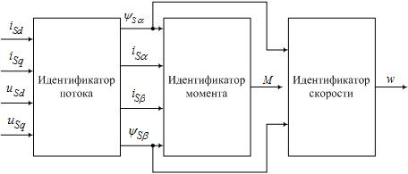
To determine the coordinates of electrical drive in the simplest case can be used by the identifier presented in Figure 1, which contains a closed thread identifier of flux with the PI correction,
as well as identifiers torque and speed, constructed in accordance with the expressions:


Figure 1 - Block diagram of the identifier of coordinates
Studies by mathematical modeling (Figure 2) showed that the origin identifier provides sufficient accuracy. Recovered signals can generally be used to organize regulation for phasing
out the use of mechanical sensors on the shaft of PSDM, as well as for improving the control algorithm.

Figure 2 - Identification of the origin of the system of vector control PSDM
Conclusions and future research
We are developing a system of vector control PMSM. The generalized functional diagram of the vector torque control, speed and angular position of the rotor PMSM presented in Figure 3.
The implementation of vector control involves the implementation of the
properties of frequency-current control. That is, the more accurate and high-speed vector control subsystem will shock, the better the system can be constructed.
Currently, these two ways: PI-regulation of current in the rotating coordinate system, on-off control current in phase coordinates [6].

Figure 3 - Generalized functional diagram of the vector control of PMSM
При написании данного автореферата магистерская работа не завершена.
When writing this Autosummary master work was not completed. The final work can be obtained from the author or supervisor since December 2010.
References
1. Майборода В. Н. Исследование сервоприводов на основе синхронных машин с постоянными магнитами (
http://masters.donntu.ru/2008/eltf/mayboroda/diss/index.htm)
2. Ищенко И. В. Исследование систем управления электроприводами на основе вентильных двигателей
(http://www.masters.donntu.ru/2009/eltf/ishchenko/diss/index.htm )
3. Божко В.В., Толочко О.І., Чекавський Г.С. «Аналіз впливу перехресних зв'язків в
системі векторного керування СДПМ»
4. Сарычев А.П., Портной Ю.Т., Раскин Л.Я. и др. «Векторное бездатчиковое
управление электроприводом на базе СДПМ»
5. Корельский Д.В. «Обзор современных методов управления СДПМ»//Радіоелектроніка. Інформатика. Управління. - 2001. №2 - с.155-159
6. Соколовский Г. Г. Электроприводы переменного тока с частотным регулированием. – 265 с.
7. Казачковський М. М. Комплектні електроприводи. – Дніпропетровськ, Обліково-видавн. 2003. – 224 с.
8. Герман-Галкин С. Г. Компьютерное моделирование полупроводниковых систем в MATLAB 6.0. – СПб.: КОРОНА принт, 2001. – 320 с.
9. Овчинников И. Е. Вентильные электрические двигатели и привод на их основе (малая и средняя мощность): Курс лекций. СПб.: КОРОНА-Век, 2006. – 336 с.: ил.
10. Виноградов А.Б. Векторное управление электроприводами переменного тока/ГОУВПО «Ивановский государственный энергетический университет имени В.И. Ленина». - Иваново, 2008. - 298с.
DonNTU >
Master's portal of DonNTU >
About author

