 |
 |
 |
 |
 |
 |
Artificial neural network based fault identification scheme implementation
for a three-phase induction motor
Sri R. Kolla, Shawn D. Altman
Electronics and Computer Technology Program, Department of Technology Systems, Bowling Green State University, Bowling Green, OH
Источник: http://hinari-gw.who.int
Abstract
This paper presents results from the implementation and testing of a PC based monitoring and fault identification scheme for a three-phase
induction motor using artificial neural networks (ANNs). To accomplish the task, a hardware system is designed and built to acquire threephase
voltages and currents from a 1/3 HP squirrel-cage, three-phase induction motor. A software program is written to read the voltages and
currents, which are first used to train a feed-forward neural network structure using the JavaNNS program. The trained network is placed in a
LabVIEWTM based program formula node that monitors the voltages and currents online and displays the fault conditions and turns the motor
off. The complete system is successfully tested in real time by creating different faults on the motor.
c 2007, ISA. Published by Elsevier Ltd. All rights reserved.
Keywords: Artificial intelligence; Neural networks; Induction motor; Faults; Protection; Relays
1. Introduction
The three-phase induction motor is a workhorse of the
manufacturing industry. This motor may encounter several
fault conditions, which can damage the motor. These
conditions include overload, unbalanced supply voltage, locked
rotor, single phasing, undervoltage, and overvoltage [1].
Microprocessor based protective relays are used to monitor
these motors and disconnect them during faults [2]. The recent
trend in microprocessor based relays is to use artificial neural
network (ANN) based techniques [3].
Elmore and Kramer [4] proposed microprocessor relay
technology for protection of motors. Lacroix and Clegg [5]
used microprocessors to identify the kinds of faults that occur
in three-phase motors. Pandurangavittal, Fakruddin, Rao, and
Parthasarathy [6] designed and built a microcontroller based
three-phase induction motor relay that provides an operator
selectable thermal I –T (current versus time) curve feature.
Farag and Kamel [7] designed and implemented a standalone
microcontroller based digital protection system using an
MC-8031 controller for three-phase induction motors.
et al. applied ANNs for the detection of incipient faults in
single-phase induction motors in the early 90’s [8,9]. They
identified stator winding faults and bearing wear using ANNs.
The motor current and speed were used as inputs. Kolla and
Varatharasa used ANNs for fault identification in a three-phase
induction motor [10]. They used software simulation to produce
data to train an ANN to determine some of the main faults in
an induction motor. Offline testing results for that scheme using
simulated data showed promising results. Different stator fault
monitoring techniques for induction motors are reviewed in a
recent paper by Siddique et al. [11]. An extensive list of 183
references on this topic is given in that paper.
The proposed work in this paper implements the ANN based
fault identification scheme in hardware and tests it in real time.
A 1/3 HP squirrel-cage, three-phase induction motor is used
for this purpose. Section 2 reviews concepts of induction motor
faults and artificial neural networks, and previous methods
of ANN use for fault identification [10]. Details of the
proposed hardware system are described in Section 3. Section 4
describes the training of feed-forward ANNs with threephase
voltages and currents using the JavaNNS program [12].
The development of LabVIEWTM [13] based software for
testing the complete fault identification system is described in
Section 5. Section 6 offers some concluding remarks.
2. Induction motor fault identification using an ANN An induction motor may experience several kinds of faults during its operation [1]. The main kinds of faults include overloading, single phasing, unbalanced voltage, locked rotor, ground fault, undervoltage, and overvoltage. A detailed discussion of these faults is given in Kolla and Varatharasa [10].
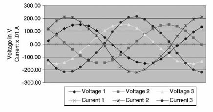
From this information it can be noted that the motor voltages and currents have distinct characteristics during these faults. For example, in the case of single phasing, one phase current is zero and the other two-phase currents have equal magnitude with a 180_ phase difference while the three-phase voltages have equal magnitudes with 120_ phase difference between them, as shown in Fig. 1. The three-phase voltage and current information is used in identifying faults using ANNs in this paper. While the applicability of the ANN method for identifying various simulated faults is demonstrated in [10], the
present work implements the ANN scheme and tests it in real time for those faults that do not damage the motor. The ANN tries to mimic the biological brain neural network in a mathematical model [14]. It is a collection of simple processing units, mutually interconnected, with weights assigned to the connections. By modifying these weights according to a learning rule, the ANN can be trained to recognize a pattern given the training data. Fig. 2 shows the simple processing unit in which the process is done by adding the input signals after multiplying by their link’s weight and the total is transferred to the transfer function part of the neuron.
There are several transfer functions such as tanh, sigmoid, etc. There are several kinds of neural network structures proposed in the literature [15]. A feed-forward network is shown in Fig. 3. There can be several hidden layers in the network. The figure shows one hidden layer. In this network, the number of input nodes and the number of output nodes are determined by the number of patterns to be identified. The number of nodes in the hidden layer is selected for an application, generally using a trial and error method. The neural network has to be trained so that it can identify the output patterns corresponding to the input pattern. There are several kinds of training algorithms suggested in the literature [15]. The back-propagation is one of the most popularly used algorithms. In this paper a feedforward network is used, and it is trained with the backpropagation algorithm. JavaNNS software [12] is used to create and train the network. While there are many different ANN
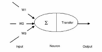
Fig. 2. Simple processing unit.
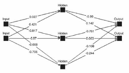
Fig. 3. Feed-forward neural network.
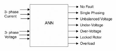
Fig. 4. Inputs and outputs of the ANN.
There is one hidden layer, and the number of neurons in that layer is varied during training. Fig. 4 illustrates the inputs and outputs of the ANN.
3. Induction motor fault identification system set-up
The complete hardware system for induction motor fault identification is developed using the set-up shown in Fig. 5. A block diagram of this system is shown in Fig. 6. In this system, the motor is connected to a three-phase supply through three VARIACS connected in a star fashion. A signal conditioning
circuit that reduces the three-phase voltages and converts threephase currents into voltages proportional to the currents is used. The signal conditioner uses a voltage transducer to step the voltage down, and a circuit is made so that it produces a voltage proportional to the motor currents. A second-order active low-pass Butterworth filter is used so that only low frequency signals are passed to the DAQ board on the National Instruments SCXI 1000 chassis [13]. The motor used for this study is a 1/3 HP three-phase squirrel-cage induction motor. The SCXI chassis contains simultaneous sampling analog input module 1140 to collect the voltages and currents, and eight-channel power relay output module 1161 to simulate circuit breakers. The chassis communicates with multifunction I/O card PCI-MIO-16E-1 placed in the PC. A Prony brake is used to simulate various loading conditions. A LabVIEWTM program is written to simultaneously acquire the signal conditioned instantaneous motor voltage and current data values. The program acquires data at a sampling rate of 1000 scans/s. The program then converts these data values into RMS values. These signals are used to train and test the ANN based fault identification scheme.
4. Training of the ANN for fault identification
The ANN structure shown in Fig. 4 is trained with the data sets obtained from the actual faults created on the induction motor. This study uses the RMS values of voltages and currents as inputs to the ANN. A total of 788 input patterns corresponding to different faults, as described in Table 1, are used. The no-fault’s 154 patterns represent various load conditions ranging from no load to full load at selected increments of load. The single-phasing fault’s 85 patterns represent each of the three phases removed separately with different loads. Similarly the remaining fault pattern represent various possible combinations for each fault. The JavaNNS program [12] is used to build and train the ANN structure offline and to determine the appropriate number
Table 1 Number of training patterns per fault
Condition Number of patterns
No fault (NF) 154
Single phasing (SP) 85
Unbalanced voltage (UB) 450
Undervoltage (UV) 49
Overvoltage (OV) 10
Locked rotor (LR) 10
Overload (OL) 30
Total 788
of neurons in the hidden layer. A screen shot of the JavaNNS program is shown in Fig. 7. The process of constructing the network involves adding the input layer to the network by selecting the unit type as input, the height of six for the number of neurons in the layer, and the sigmoid transfer function, which is called the logistic function in JavaNNS. Then the hidden layer is added by selecting the sigmoid function, hidden unit type, and various numbers for the hidden layer neurons. For this study, the best results are achieved using eight hidden layer neurons. As explained in Section 2, selection of the number of neurons in the hidden layer is a trial and error process based on achieving the best training of the network.
The last layer is added by selecting the unit type output, the height of seven for the number of neurons in this layer, and the sigmoid transfer function. Once the ANN structure is constructed, the training process involves choosing parameters for _ (momentum coefficient) and _ (learning coefficient) by trial and error, when using back-propagation with momentum algorithm. JavaNNS also includes a maximum non-propagating error and flat spot eliminator, which worked best when set to zero in this study. This study tried numbers 0.1–0.9 in increments of 0.1 for the momentum and learning coefficients and had the best results with 0.1 for _ and 0.1 for _. After 160,000 training iterations for the ANN structure, the sum of squared errors (SSE) reduced to 0.013284. The training of the ANN is performed offline. The number of iterations and the time it takes for these iterations will not have any effect on the online identification of faults.
After the network is built and trained it is saved, along with the biases, weights, and the log file. This file is used as an input to a program that is written in Visual Basic to change the trained ANN into a C-program based LabVIEWTM formula node that is used to determine the current state of the motor based on the data read into the computer.
5. Testing of ANN based fault identification system Online testing of the system involves adding the LabVIEWTM code to read the data in real time and pass the
Fig. 6. Block diagram of complete fault identification system.
6. Conclusions
This paper described the implementation and testing of a PC based fault identification scheme for a three-phase induction motor using the ANN. To accomplish this, a hardware system was designed and built to acquire three-phase voltages and currents from an induction motor. A 1/3 HP squirrel-cage
three-phase induction motor was used to create faults and collect data for training and testing the ANN based system. A
Acknowledgements
The authors thank Drs. David Border and Erik Mayer of the Electronics and Computer Technology Program, Department of Technology Systems, Bowling Green State University, for their helpful suggestions on this work.
References
[1] ABB Relaying Division. Protective relaying: Theory and application. New
York (NY): Marcel Dekker, Inc.; 1994.
[2] Phadke AG, Thorp JS. Computer relaying for power systems. New York
(NY): John Wiley & Sons; 1988.
[3] Sachdev MS. (Coordinator), Advancements in microprocessor based
protection and communication. IEEE tutorial course text. Publication no.
97TP120-0, New York (NY); 1997.
[4] Elmore WA, Kramer CA. Complete motor protection by microprocessor
relay. In: Proceedings of Georgia tech protective relaying conference.
1987. p. 1–13.
[5] Lacroix B, Clegg D. Microprocessor motor protection relay. In:
Proceedings of 4th international conference on developments in power
system protection. IEE Pub. No. 302. 1989. p. 235–8.
[6] Pandurangavittal K, Fakruddin DB, Rao IR, Parthasarathy K. Microcontroller
based three-phase induction motor protection relay with operator
selectable thermal I –T curve feature. Electric Machines and Power Systems
1998;26:13–26.
[7] Farag WA, Kamel MI. Microprocessor-based protection system for threephase
induction motor. Electric Machines and Power Systems 1999;27:
453–64.
[8] Chow M-Y, Yee S-O. Using neural networks to detect incipient faults in
induction motors. Journal of Neural Network Computing 1991;2:26–32.
[9] Chow M-Y, Sharpe RN, Hung JC. On the application and design of
artificial neural networks for motor fault detection. IEEE Transactions on
Industrial Electronics 1993;40:181–96.
[10] Kolla SR, Varatharasa L. Identifying three-phase induction motor faults
using artificial neural networks. ISA Transactions 2000;39:433–9.
[11] Siddique A, Yadava GS, Singh B. A review of stator fault monitoring
techniques of induction motors. IEEE Transactions on Energy Conversion
2005;20:106–14.
[12] Fischer I, Hennecke F, Bannes C, Zell A. JavaNNS. http://www-ra.
informatik.unituebingen.de/JavaNNS/, 2001.
[13] National instruments, LabVIEW requirements. www.ni.com/labview/
requiremts/, 2003.
[14] Lau C, editor. Neural networks: Theoretical foundations and analysis.
New York (NY): IEEE Press; 1992.
[15] Caudill M, Butler C. Understanding neural networks: Computer
explorations. Cambridge (MA): MIT Press; 1992.
[16] Altman SD. Real-time implementation of a fault identification scheme
for a three-phase induction motor using artificial neural networks. M.I.T.
thesis. Bowling Green (OH): College of Technology, Bowling Green State
University; 2004.
