Model and Control of Renewable Energy Systems
Yelena Chaiko
http://www.waset.org/journals/waset/v39/v39-27.pdf
Abstract – This paper presents a developed method for controlling multi-renewable energy generators. The control system depends basically on three sensors (wind anemometer, solar sensor, and voltage sensor). These sensors represent PLC's analogue inputs. Controlling the output voltage supply can be achieved by an enhanced method of interlocking between the renewable energy generators, depending on those sensors and output contactors.
Keywords – Renewable, energy, control, model, generator.
I. Introduction
Renewable energy is any source of energy that can be used without depleting its reserves. These sources include sunlight or solar energy and other sources such as wind, wave, biomass and hydro energy. The renewable energy generators consist of four generators, which supply two bus bars. Two DC generators are supplying the DC bus bar, and two AC generators are supplying the AC bus bar. The control system consists of four contactors. Each contactor is connected to the output of a generator. That means the output voltage from any generator is supplying the contactor, which is responsible for that generator, and so on for the rest of the contactors. Control of these contactors occurs by controlling the interlock between these contactors, depending on the resources used (wind, solar, batteries bank, diesel generators). The control system can be achieved by means of a Programmable Logic Controller (PLC) Allan Bradley 500 series for hardware. The communication between PC and PLC occurs by using RSLogix 500 (Rockwell Software), which contains RSLinks (Rockwell Software). The fixed controller provides the power supply, inputs, outputs, and processor in one unit. It also offers a 2-slot expansion chassis for increased flexibility. The programming tools and most I/O modules are compatible between the two hardware options renewable energy generator's control system. [1-5]
The SLC 500 line offers a range of choices in memory, I/O capacity, instruction set, and communication ports to implement a control system to exact application requirements. These products have a strong reliability history covering hundreds of thousands of installations in a broad range of applications. Fig. 1 shows the layout of the I/O boards (slots 1 - 7), processor (slot 0), and power supply for SLC 500 of the renewable energy generator's control system. [1-5]

Fig. 1 SLC 5/04 Controller
II. System Description
Three analogue sensors (wind anemometer, voltage sensor, and solar sensor) are connected to slot 3 containing four channels via loop-powered method. This means the analogue inputs are connected to PLC in series. For example, a reading of 4 ma (minimum value) corresponds to an integer number 3277, and 20 ma (maximum value) corresponds to an integer number 16384.
There are 13 digital inputs to slot 1 (24 VDC), with three spares. Slot 2 has 6 digital inputs (24 VDC), with 10 spares. The co-relation of both analogue and digital inputs according to the program determines the correct selection of output contactor, as a renewable generator activates (e.g. wind, solar, voltage level). Having achieved which system comes on line the processor, through slot 4 activates the coil to that particular generator unit. [6-78]
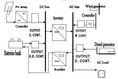
Fig. 2 shows typical renewable energy generators are consisting of four generators. If the wind generator (the lead in the interlock) is producing 240 VAC (windy day) then it is supplying the output wind contactor's input terminal by 240 VAC. The activation of the output wind contactor's coil depends on the anemometer sensor and it is of a certain value (within a range). Solar generator will be deactivated, for example on a cloudy day, batteries bank generator is offline, diesel generator selected in off or auto position. When all conditions are met then the coil of the output wind contactor activated. Second generator is the solar generator; it works only when it's operating conditions are met. E.g. insufficient wind level, batteries bank voltage level low, diesel generator is set to off or auto mode and enough sun to register voltage level are within the range.

Fig. 2 Block diagram of renewable energy generators
The solar sensor gives an order through the PLC 500 to activate output solar contactor's coil, thereby it will pass the voltage from solar generator to DC bus bar. Third contactor is the batteries bank generator, this contactor activates if there are no wind, no sun, and the diesel generator in off or auto mode, then the voltage sensor (e.g. within working voltage level) which is connected to the PLC's analogue input card, give an order to the output batteries bank contactor's coil to activate so that it passes the voltage from batteries bank generator to the DC bus bar. The energizing of the fourth contactor has been achieved when there are no wind, no sun, no enough voltage from batteries bank and the generator's control switch on auto mode, then the PLC will order a command to the diesel output contactor's coil to activate so that the voltage from diesel generator will passes to the AC bus bar. If the generator's operating switch is on auto mode and the diesel generator fails to run under any condition then turn a generator's control switch to manual mode, which allow running the generator manually under the same conditions (no wind, no sun, no good voltage level from batteries bank). There is another mode on the generator's operating switch called test mode, which allows monitoring the generator's performance even if any generator is running (wind, or solar, or batteries bank generators). This can be achieved by three emergency stops, each emergency stop for each contactor, press them all to deactivate the three contactor's coils and therefore activates the output diesel contactor to allow the passage of AC voltage from diesel generator to the AC bus bar.
III. Interlock
To emphasize the relationship between the contactors, there is an interlock between the four contactors so that if the coil of any contactor activates then the other contactors cannot activate even if the operating conditions for them are available. For example if the wind generator is running due to permissible wind level then wind anemometer read the value and transfer it to the PLC's analogue input card, and other conditions are made according to the software program. As a result of that, a 24 VDC output from an output card of the PLC orders the coil of the wind contactor to activate causing the AC voltage which is generated by wind generator to pass to the AC bar, the interlock between contactors prevents solar, or batteries bank, or diesel generators to activate. The same program is implemented for other contactors, as illustrated, only one contactor will activate even the operating conditions for all contactors are available to prevent the interfering between the contactors. If wind generator stopped producing AC voltage due to low wind level, then the wind anemometer according to the set point in the software program transfer this low wind level to the PLC causing the output card to produce 0 VDC sending it to the coil of the wind contactor. As result it deactivates the wind contactor, stopping the AC supply to the AC bus bar, then the other contactor where the operating conditions are available, transferring the analogue value to the input analogue card of the PLC. As a result it will order the output card to produce 24 VDC to the coil of that contactor to activate it, causing a passage of the supply voltage of that generator to a specific bus bar. On a sunny day, the solar generator is producing DC supply, because there is an interlock between generators, solar contactor's coil was not activating until solar sensor indicates a permissible level of sun light to transfer it to PLC's analogue input card, therefore an output of 24 VDC generated to activates solar contactor's coil, then it passes the DC supply from solar generator to a DC bus bar. The solar contactor would not start immediately to protect the load from sudden voltage supply, delay the other contactors start up by delaying the timer for couple seconds up to minutes until voltage settles down.
IV. Developed Method
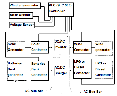
Fig. 3 shows a block diagram for a control-developed method of three renewable energy generators and emergency LPG or diesel generator, controlled by PLC. The control method depends on three analogue sensors (wind anemometer, solar sensor, voltage sensor), Allen Bradley SLC 500, and four output contactors as shown in highlighted block in Fig. 3.

Fig. 3 Block diagram of a control developed method
These three analogue sensors are connected to the analogue input card of SLC 500 (Allan Bradley). Any reading via any sensor will transfer it to the analogue input card. By loop powered method all the sensors are connected in series with the analogue input card. Fig. 4 shows the relationship between the input value and scaled value, for example (30 – 180) Km/h is the operating zone of wind anemometer so that it energized the output wind contactor, which is corresponded to 4mA and 20mA respectively. This analogue input is connected to card 3, channel 1. Below 30 Km/h and above 180 Km/h are called the non-operating zones, which means input values are below 4mA and above 20 mA. These out range values are deactivated the output wind contactor. While the operating zone starts with a wind speed equal to 30 Km/h, then the input value to the PLC is 4 mA which is equal to integer 3277, second point at wind speed 80 Km/h, the input value to the PLC is 8mA which is equal to integer 7646, third point at wind speed 130 Km/h, the input value to the PLC is 16mA which is equal to integer 12015, at the last point, wind speed value in the operating zone is 180 Km/h, the input value to the PLC is 20mA which is equal to 16384. [6,7]
VI. Conclusion
This paper has demonstrated the control development method of combination of three renewable energy generators and backup diesel generator: using three analogue sensors for wind, solar, and batteries bank, three contactors for three renewable generators and the fourth contactor for diesel generator, Allen Bradley PLC (SLC 500), and RSLogix 500 as software. The developed method can be summarized by:
- Natural resources like wind; sunlight activates the contactors coils via their analogue sensors (wind anemometer, solar sensor). These sensors and batteries bank voltage level sensor, connected to the analogue input card of the PLC to generate output to each contactor's coil. While the diesel contactor's coil actuation depends on failure of all other renewable energy contactors.
- To prevent any interference between the contactors, interlock has been used between them.
- Because the control method is PLC driven method, then controlling the renewable energy generators remotely can be achieved by SCADA system via telephone line and modem.
References
- UNESCO Headquarters, World Solar summit, Energy and Hydrogen (Solar Hydrogen), UNESCO Publication Paris, 5-9 July 1993.
- Eurosolar Publication. The Yearbook of Renewable Energies, published in collaboration with UNESCO. Ponte Press, Bochum, 1992.
- Leyden Deer, Catriona Johnson, Energy Use In Commonwealth Operations 1998-99, Energy and Environment Division Department of Industry, Science and Resources, March 2000.
- Allen Bradley publication 1747-6.15, reference manual, for SLC 500 and micrologix 1000 instruction set, Allen Bradley company, January 1996.
- Allen Bradley publication, SLC 500 Analogue I/o modules, Allen Bradley Company IC-942-March, 1993.
- Allen Bradley publication, 1746 - 6,4 - Allen Bradley Company, January 1996.
- Rockwell Automation, RSLogix 500, Programming for the SLC 500 and MicroLogix Families, Rockwell Software INC, USA, 1998.