
| Индивидуальный раздел | Главная | Реферат | Библиотека | Ссылки | Отчет о поиске |

Казаков Олег Владимирович
Факультет компьютерных информационных
технологий и автоматики
Кафедра электронной техники
Специальность: Электронные системы
Руководитель: доцент, к.т.н. Винниченко Н.Г.
Тема магистерской работы: Обоснование и исследование структурной
схемы электронной системы
контроля натяжения канатов шахтных
подъемных установок
Structural failures of rope-based systemsG. Piskoty, M. Zgraggen, B. Weisse, Ch. Affolter, G. TerrasiEmpa, Swiss Federal Laboratories for Materials Testing and Research,
|
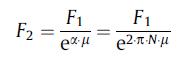 |
(1) |
α: Enlacement angle of the rope around the drum, μ: friction coefficient between the rope and the drum’s surface, N: number of windings.
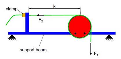
Fig. 2. Construction of the anchor drum.
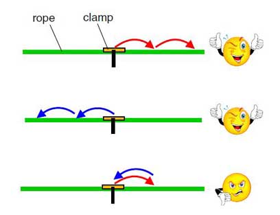
For example, if the friction coefficient is 0.2 and the rope is wrapped around the drum four times, the residual force amounts to only 1% of the service load (F2 ≈ F1 / 100). In general, the clamp has to be designed just for a small fraction of the service force in the rope, allowing a smooth clamping, without excessive local pressure on the rope’s surface. This advantage becomes especially important for applications where the rope has to be shifted periodically as in the final case study in
this paper.
3.2. Accident
During regular operation of a ropeway, the end of a hauling rope holding the cabin in position slipped off the clamp of the anchor drum. The rope detached from the cabin and the cabin became free. Fortunately, a safety equipment (track rope break [1]) prevented the crash of the cabin.
3.3. Investigations
The visual inspection of the anchor revealed no apparent anomalies. As an excessive overload during operation could be excluded, an insufficient load capacity of the anchorage was assumed. This obvious hypothesis had to be proved with a load test. Since the rate of change of the service load in the rope was low, a quasi-static test set-up was built. During the test, the force in the anchored rope was increased gradually up to the triple of the highest service load. However, the clamp did not fail. The hypothesis of insufficient load capacity of the anchor had to be rejected.
At a loss to explain the failure and test result, the disassembly of the test set-up was started. At first, the load in the rope was removed. In doing so, a small amount of slippage was observed between the clamp and the rope. By repeating the loading and unloading cycle, the rope slipped incrementally through the clamp, even when the fluctuating tensile force in the rope remained considerably below the regular operational force. Strangely enough, the slippage took place not during the increase but during the reduction of the load.
The unexpected system behaviour could be explained after a detailed analysis of the process. The service load fluctuated slowly in accordance with the load status, position or acceleration of the cabin etc. within a regular range. If the tensile load increased, the elastic deflection of the support beam became larger. As a consequence, the distance between the drum and the rope clamp decreased (F1 ↑ → k ↓, Fig. 3). Due to the reduced distance, the residual force collapsed (k↓ → F2↓), and therefore the relationship (1) was no longer satisfied. In order to restore the required equilibrium between the forces on the both side of the drum, the rope crept around the drum in a clockwise direction until the residual force increased to the required value again.
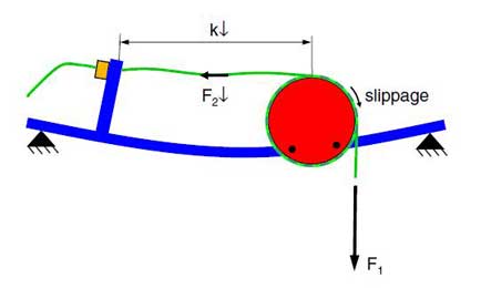
Fig. 3. Disturbed force equilibrium in the rope on both sides of the drum during increased service load (the elastic deformation of the support beam is exaggerated).
When the operational load decreased, the support beam started to flex back into its original position. Therefore, the distance between the drum and the clamp got larger (F1 ↓ → k ↑). Because of the missing rope length between the drum and the clamp, the load started to increase in that rope section. There was no possibility for pulling back the rope over the drum, as it would have required a force several times higher than the current service load (interchanged indices ‘‘1” and ‘‘2” in Eq. (1)). Obviously, the yielding took place at the clamp which was designed just for a small fraction of the service load. During the operation of the ropeway this asymmetric procedure was repeated periodically, until the rope had slid out of the clamp.
3.4. Generalized conclusions
Structures should be analysed also under consideration of fluctuating service loads, even if classical dynamic failure causes – such as vibrations, fatigue or wear – can be excluded.
A failure can be caused by hidden coupling effects in a system.
A simple elastic structure can react to a variable load with asymmetric behaviour. This can lead to the accumulation of small negative effects and finally cause failure.
4. Summary
The generalised conclusions given in this paper represent only some possible examples of how the knowledge of a particular failure analysis can be generalised and collected in order to support future investigations. In this way, the experience made by a failure analysis can be strengthened in one’s memory. Furthermore, it becomes more recallable and applicable for different kinds of failed systems. As a result, the efficiency of the failure analysis procedure increases and the likelihood of incorrect conclusions decreases.
Acknowledgements
The second failure was originally investigated under the leadership of Prof. Dr. G. Oplatka, retired head of the Institute of Ropeway Technology at the Swiss Federal Institute of Technology Zurich (ETH-Z). The authors thank him for providing the background information for this paper.
Literature
- Wallis-Tayler AJ. Aerial or wire rope-ways: their construction and management. Kessinger Publishing, LLC; 2007.
- Eidgenössisches Verkehrs, Energiewirtschaftsdepartement. Pendelbanhnverordnung. Bern: Eidgenössische Drucksachen – und Materialzentrale; 1988.
- Kuron D. Wasserstoff und Korrosion. Kuron Verlag; 2000.
- Lange G. Systematische Beurteilung technischer Schadensfälle. DGM-Verlag; 1993. p. 235 ff.
- Ashby MF, Jones DRH. Eng Mater 1. 3rd ed. Elsevier; 2005.