Yuriy Blinov
Faculty of Computer Science and Technology
Speciality: Computer Systems and Networks
"Development and research FPGA-based methods and structures of hardware tests generation and analysis of test responses"
Development and research FPGA-based methods and structures of hardware tests generation and analysis of test responses
Contents
- Introduction and relevance
- Purpose and objectives of the Master
- Scientific novelty
- Principles of digital test
- Methods of test pattern generation
- Analysis of test responses
- The structure of the logic analyzer
- Results of the work
- Conclusions
- References
Introduction and relevance
The problem of digital testing and diagnosis has become important with the start of production of the first digital devices. The process of production of schemes almost completely automated, though it does not guarantee the quality of each manufactured chip. The causes of defects, among others, could serve as impurities and defects in materials, equipment malfunctions or human error.
There are many classes of devices, the requirements for proper operation of which are particularly critical. One way to ensure reliability, both during production and during operation is the use of methods of technical diagnostics to enable monitoring, fault isolation and restoration of equipment by replacing a faulty unit or device.
An important parameter when testing devices is the speed of testing. There are automated test equipment (ATE) allowing to operate at frequencies equal to tens of gigahertz[2]. These devices are expensive, massive and stationary, which limits their application. Therefore, the subject of this master's work, aimed at the development and research of methods and structures of the hardware test patterns generation and analysis of responses from device under test (DUT), using all the advantages of FPGA technology is quite relevant.
Purpose and objectives of the work
Aim is to develop structures and methods for automatic test patterns generation and analysis of responses. To achieve this goal there are following tasks:
- study of existing methods and systems for testing;
- development of methods and structures for FPGA-based test pattern generation;
- development of methods and FPGA-based structures for analysis of responses from DUT;
- research of experimental systems which were developed.
Scientific novelty
Alleged scientific novelty is in the development of methods and FPGA-based architectures of the test pattern generator and responses analyzer in order to permit testing of high-speed digital devices. It is expected that the system will provide a sufficiently high speed, compact, versatile and low cost.
Principles of digital testing
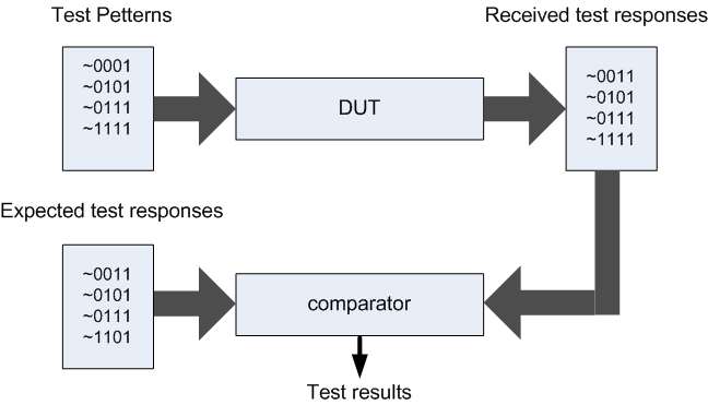
Figure 1 demonstrates the basic principle of testing.

The figure shows that the test patterns are sent to the circuit inputs. If there are differences between obtained and expected responses, then the device is broken. Testing is done with automated system, which in itself can be a very complicated device.
Methods of test pattern generation
The process of testing consists in sequential applying test patterns ti, i = 1..N, of a set T = (ti), called the test. The sequence of test patterns may be important or not. Depending on this characteristics there’re following methods of test patterns generating[1]:
- exhaustive;
- pseudorandom ;
- deterministic;
- combined.
Exhaustive testing
In exhaustive testing, test T consists of 2n of various input test patterns, where n - number of circuit inputs. This method is very simple to implement, because could be implemented using a binary counter. However, it is not applicable to sequential circuits, due to bad correlation properties of exhaustive test.
Pseudorandom testing
In pseudorandom testing is also generated test, close to exhaustive, but, unlike the last sequence of pseudorandom test patterns have properties similar to those of a random sequence.
Pseudorandom tests can be generated using a Linear feedback shift register (LFSR)[9].
In order to build Linear feedback shift register two similar structures are used. Figure 2 shows LFSR adders with external feedback, as Figure 3 shows LFSR adders with internal feedback[3].


An important characteristic of LFSR is a repetition period of the generated sequence, which depends on the kind of feedback described by a polynomial of the feedback G(x). Longest sequence that can be generated called sequence of maximum length, or M-sequence[3].
Genetic algorithms
Relatively new method of generating pseudorandom testing is a method which uses genetic algorithms[4]. Using genetic algorithms for the generation of control tests is a natural development of pseudo-random test generation techniques. Genetic algorithms, as one of the paradigms of evolutionary computation, are built on principles similar to the principles of natural selection. These principles are based on these mechanisms of evolution:
- first principle of genetic algorithms is based on the concept of survival of the fittest and natural selection of Darwin.
- second principle of genetic algorithms is due to the fact that the chromosome of a descendant is composed of parts derived from the chromosomes of the parents.
- third principle is used by genetic algorithms, based on the concept of mutation. By analogy with this principle, genetic algorithms use a similar mechanism to change the properties of their descendants and, thus, increasing the diversity within a population (the set of solutions).
These three principles form the core of genetic algorithms. Simple genetic algorithm uses three main operators: reproduction, crossing-over, mutation.
Obviously, individuals (chromosomes) in this case is a separate set of binary values of scheme input variables[7]. Populations is the set of combinations that make up the check test scheme. The fitness function can be considered as the number of tested them malfunctions.
Pseudo-random testing allows a high probability of failure to cover the combination of simple and weakly sequential circuits. The effectiveness of this type of testing decreases with increasing complexity of the DUT, and for complex circuits it is almost unacceptable to discovers, as such schemes require a strictly regulated sequence of test actions. For such circuits deterministic tests are used.
Deterministic Test
In deterministic testing all test patterns are strictly defined. If the sequence of test vectors is also important, the test is strictly deterministic, if the order can be arbitrary, the test is called weakly deterministic.
Weakly deterministic tests
For weakly deterministic test T restrictions on the order of test patterns are removed. Obviously, the two tests with different order of the test patterns have the same ability to detect errors. Such kind of tests can be used only for combinational circuits, since for them does not matter the order of input test patterns.
Generators of weakly deterministic tests include[1]:
- generators based on the ROM and linear sequential machines ("LSM+ROM ")
- ROM, counter, and the driver "ROM+CT+D")
- generator based nonlinear feedback shift register (NFSR)[10].
Strongly deterministic tests
Unlike previously discussed, to generate strictly deterministic test only one structure can be used, which is based on n × m memory block. For strictly deterministic tests sequence of test patterns is defined. This kind of generators allows high performance for testing of digital circuits of any complexity. However, even testing of simple DUT requires large hardware costs.
Thus, analysis methods and tools for generating exhaustive, pseudorandom and deterministic tests are characterized by slightly more compact, but are not effective for highly-sequential circuits. Strictly deterministic tests, on the contrary, provide testability circuits of any complexity, but there are no methods of compact generating.
Combination Tests
An obvious approach to overcome these shortcomings is the usage of combined methods of testing, which are based on a combination of strictly deterministic and other types of test generator.
Analysis of test responses
An analysis of test responses by comparing the received response with the predefined, which can be obtained either from the physical device, or its logical model. Сomplete response or their compressed equivalents (signature) can be used. There are following basic methods of reactions analyzing:
- logical analysis;
- compact analysis.
- signature analysis — based on the compression of responses using a feedback shift register.
- state binary counter calculates the number of ones and zeros
- binary counter calculates the number of transitions from 0 > 1 or 1 > 0
The structure of the logic analyzer
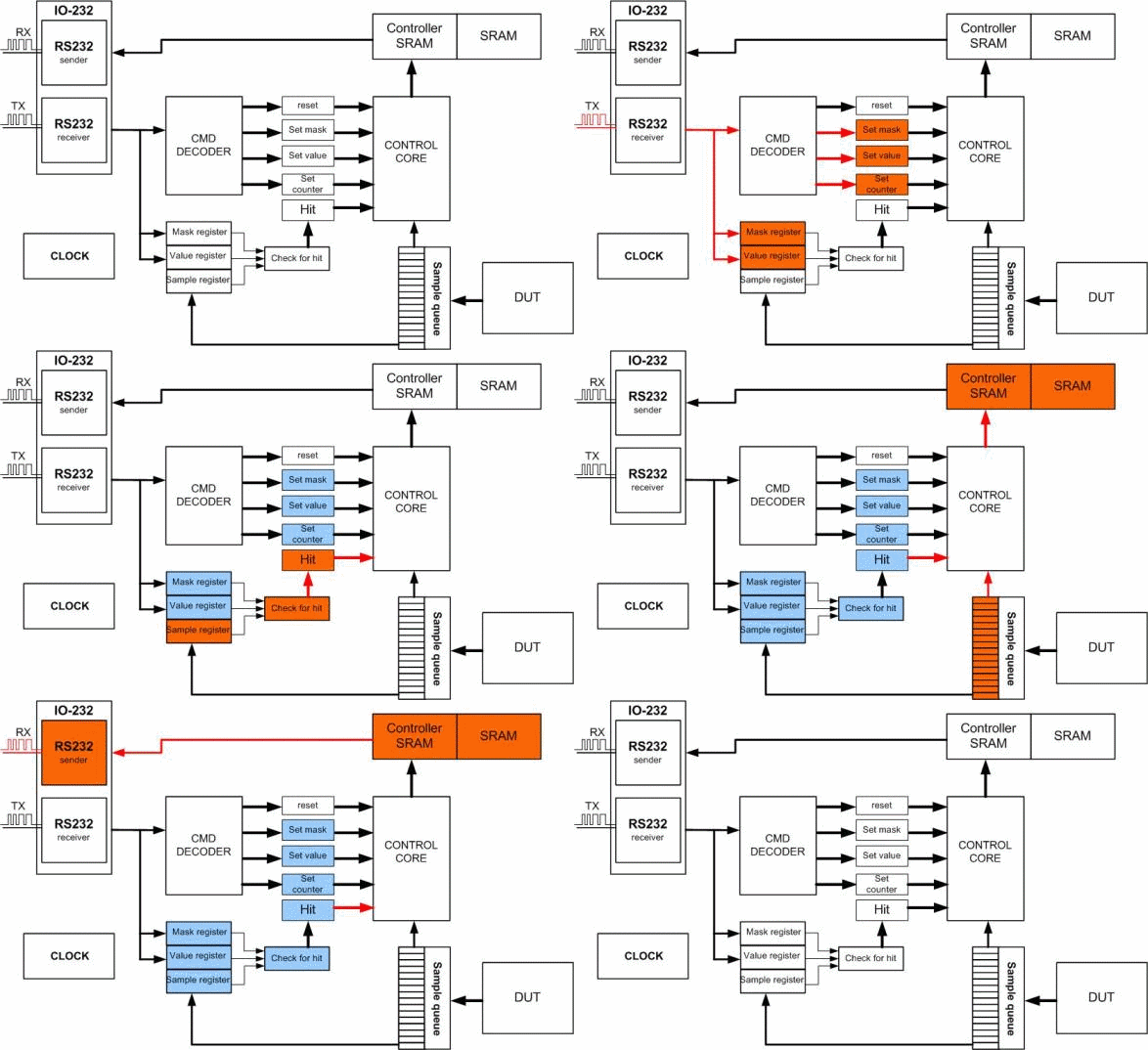
At the time of writing this work I have developed logic analyzer based Spartan-3E starter cit. A simplified structure of the developed logic analyzer is given in Figure 4.

(GIF-animation, size: 85kbyte, frame number: 6, times to repeat: 5)
Logic analyzer is an electronic instrument which displays signals of a digital circuit which are too fast to be observed and presents it to a user who can then precisely observe with greater ease the operation of the digital system under test. It is typically used for capturing data in systems having too many channels to be examined with an oscilloscope[6].
The developed device has the following working principle:
- user using the client software selects and sets the necessary parameters, which are used to select signals from DUT.
- when all the necessary parameters are set, the device awaits the appearance of a given type of signal on external output of the DUT.
- then specified count of responses are saved to memory.
- data is transmitted to the user client software.
- device goes into standby for further instructions.
Results of the work (the writing of the abstract)
At the time of writing the abstract the following results are obtained:
- completed review of existing methods for testing digital circuits;
- selected FPGA-board for planned project;
- completed development of the logic analyzer;
Conclusions
Based on the foregoing material it can be concluded that:
- development and research methods and structures of the hardware test generation and analysis of responses is still relevant;
- based on data characteristics and descriptions of methods of generating test vectors and analysis of test reactions conclusions about choice of methods for testing different classes of devices are maid;
- as a platform for the implementation was chosen Spartan-3E FPGA-board.
References
- Зинченко Ю.Е. Методы и средства встроенного тестового диагностирования специализированных устройств сетей передачи данных реального времени / Ю.Е Зинченко // Диссертация на соискание уч. степени канд. техн. наук.; специальности: 05.13.13 "Вычислительные машины, комплексы, системы и сети" и 05.13.05 "Элементы и устройства вычислительной техники", Институт проблем моделирования в энергетике (ИПМЭ) АН Украины. — Киев, 1989, 208c.
- Agrawal V.D. Essentials of electronic testing for digital, memory and mixed-signal VLSI circuits./V.D.Agrawal // Kluwer Academic Publishers, 2000, — 690c.
- Зинченко Ю.Е. Разработка компьютерных систем на базе ACTIVE-HDL, методические указания [Electronic resource] Access mode: http://hardclub.donntu.ru/methods/nkd/nkd_mu/MAIN.HTM
- Скобцов Ю.А. Логическое моделирование и тестирование цифровых устройств/ Ю.А.Скобцов, В.Ю. Скобцов // Донецк: ИПММ НАН Украины, ДонНТУ,2005. — 436с.
- Ivask E., Raik J., Ubar R. Comparison of Genetic and Random Techniques for Test Pattern Generation [Electronic resource] Access mode: http://www.citeseerx.ist.psu.edu/viewdoc/download?doi=10.1.1.59.8973
- Перцовский М., Воробьев Е., Трифонов А. Применение логических анализаторов в тестировании цифровой техники [Electronic resource] Access mode: http://www.cta.ru/cms/f/?/366656.pdf
- Уколов И.В. Cинтез псевдослучайных контролирующих тестов для дискретного устройства [Electronic resource] Access mode: http://www.sgu.ru/files/nodes/37509/Ukolov(64-70).pdf
- Zhang Y., Agrawal V.D. An Algorithm for Diagnostic Fault Simulation [Electronic resource] Access mode: http://www.eng.auburn.edu/~agrawvd/TALKS/LATW10/latw10_yu_new6.pdf
- Linear feedback shift register. Википедия свободная энциклопедия [Electronic resource] Access mode: http://en.wikipedia.org/wiki/Linear_feedback_shift_register
- Non-Linear Feedback Shift Register. Википедия свободная энциклопедия [Electronic resource] Access mode: http://en.wikipedia.org/wiki/NLFSR
Note
When writing this abstract master has not yet completed. Date of final completion: December 2010. Full text of the work and materials on the subject of the work can be obtained from the author or his supervisor after that date.