Main DonNTU>> Portal of masters of DonNTU> The main page |
THE AUTHOR'S ABSTRACT
UKR RUS
Donetsk national technical university
Plygun Ekaterina Konstantinovna
Speciality: "Heat-and-power engineering "
THEME OF MAGISTRSKY WORK:
"The indesting of heating of liquids during their pumping in the independed heat supply sources with the object of operation efficiency increase."
The primary function of systems of the central heat supply is delivering of the produced warmth to consumers in the most reliable and economic way. For producing it by the pipeline systems well isolated by thermal lining are constructed, protected from external influence and the damages, equipped запорной and regulating armature,
means of automatics and the account of heat energy and heat-carriers.
Thermal network is set of the devices intended for transfer and distribution of warmth from a source to consumers.
Thermal networks the most expensive and metal-consuming constructions among engineering communications of cities, therefore they should will be executed so that could serve not less than 50 years, without demanding frequent repairs and reruns and without reducing the operational qualities in this term. These requirements form indicators of reliability and durability of systems
of the central heat supply which in turn define heat supply economy as a whole.
The enterprises of thermal networks at their operation should provide reliability of a heat supply of consumers, giving of heat-carriers with the expense and parameters according to the temperature schedule of regulation and difference of pressure on input. At designing of thermal networks there is a necessity of additional calculations
of the pressure caused by non-uniform distribution of the heat-carrier during the starting moment.
–The majority of calculations of thermal networks are made at a stationary operating mode. And at system start-up passes a non-stationary mode which can be accompanied by hydraulic blow. Therefore at the first start-up of system it is necessary to calculate an optimum mode of filling of the pipeline the heat-carrier for prevention of hydraulic blow.
–Hydraulic blow represents short-term, but sharp and strong increase of pressure in the pipeline at a sudden stop of a stream of a liquid moving on it. As a rule, this phenomenon arises at filling of pipelines when air has time to leave through specially open crane, but the section of this crane does not suffice to pass all stream of incompressible liquid which have
suddenly reached it. The same effect arises and at fast closing of the gate sharply blocking a stream. The last is especially actual today when the old screw cranes-axle boxes necessarily closed smoothly (after all to twist hand-wheel many turns and consequently the rod blocks a gate gleam slowly enough are necessary), are replaced with the modern spherical cranes "cutting" a
stream of all for a quarter of a turn by one movement of a hand.
–However hydro blows not necessarily extend on all pipes. At occurrence cavitations, every flapping cavitational a vial is accompanied by micro-hydro blow. To such hydro blows not under force to destroy all pipe at once, however their long destructive action in a zone cavitations can easily exceed a damage from powerful, but concerning rare hydro blows.
More or less considerably hydraulic blow is shown only in rigid pipelines at a stream great speed. It occurs when the moving liquid with some speed suddenly meets a rigid obstacle which, as a rule, may be a damper on the way. As a result the liquid stops, and its kinetic energy turn in potential energy of elastic compression of a liquid
(after all liquids are considered incompressible only in comparison with gases, and actually are compressed approximately in the same degree, as firm bodies with crystal structure), and also potential energy of an elastic stretching of walls of a pipe. All it leads to that pressure promptly increases in a stop place, that more than above there was a speed of a liquid and than less its compressibility, and also than above rigidity of a pipe. This increase of pressure also is hydraulic blow of suddenly stopped liquid.
Phases of development of hydroblow
How the hydroblow phenomenon develops? We will consider it on the most simple example — sudden filling with a liquid of an empty pipe of the constant section shipped on some depth. One end of this pipe is closed by a rigid cap, and another is freely informed with surrounding liquid. By the way, practically the same will be if to consider sharp overlapping of the established stream in the same pipe, only there will be no there a first phase — filling of an empty pipe, — and the cap role will play blocked a pipe.
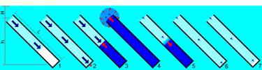
The scheme of occurrence of hydraulic blow at filling with a liquid of an empty pipe.
Blue colour designates environment with initial pressure, light blue — area of the lowered pressure, dark blue — elevated pressure area (a hydroblow zone). Dark blue arrows show moving of substance of the environment (liquid), red — moving of border of a zone of an elevated pressure (without essential moving of substance).
H — Depth (pressure) on a pipe input;
h — Difference of heights of a pipe,
L — Length of a pipe from an input to a cap. Figures designate phases of development of the phenomenon.
The table 1. Phases of development of hydraulic blow
| № Phases |
The phase name |
The phase description |
| 1 |
Pipe filling |
Under the influence of external pressure the liquid fills a pipe, thus according to the law of Bernulli its pressure is slightly less than pressure of the motionless environment out of a pipe. |
| 2 |
Meeting with an obstacle |
The rigid cap suddenly stops a stream which hits in it. However practically all liquid in a pipe still continues the advance. |
| 3 |
Growth of a zone of an elevated pressure |
The head part of a stream has stopped also its kinetic energy has passed in potential energy of elastic deformation of a liquid and pipe walls, having caused in this area pressure increase. But to stream "tail" this influence is yet cunning, and there the liquid continues to move in a former direction. The border of area of an elevated pressure (shock wave) moves from a cap to a pipe input, at sufficient rigidity of a pipe this speed is almost equal to speed of distribution of elastic fluctuations in the environment, i.e. speed of a sound in a liquid. |
| 4 |
Elevated pressure maximum |
The shock wave has reached an input of a pipe and left in the motionless environment. As environment is motionless concerning pipe walls, she any more does not add the kinetic energy and does not render essential resistance of the compressed liquid in a pipe, and that starts to move from an elevated pressure zone outside. Besides, in the free environment of a wall of a pipe any more do not limit and "do not focus" a shock wave so it extends extensively, quickly losing force. Thus, having reached a pipe input, the shock wave "dissipates" and "dies away". In more details this moment is considered more low. |
| 5 |
The beginning of return movement |
As at an input in a pipe pressure is rather low, the compressed liquid moves there under the influence of an elevated pressure in a pipe. Thus potential energy of elastic deformation again turns to kinetic energy, but movement is already directed in the opposite direction. As a result the border of a zone of a motionless liquid under an elevated pressure moves from an input to a pipe back to a cap, leaving at an input a zone a little the lowered pressure in which the liquid moves back to a pipe input. Speed of moving of this border in case of enough rigid pipe also is equal to speed of distribution of elastic deformations in the environment, i.e. speed of a sound in liquids, however pressure difference on border not such sharp as at shock wave distribution — the border zone essentially is wider. The reason of it are features of process of dispersion of a shock wave at an input in a pipe on the previous phase.
At pressure drop all potential energy of elastic deformation again passes in kinetic energy of a liquid (minus inevitable losses which can be rather small), therefore speed of the "discharged" liquid is almost equal to its speed to a stop, only is directed now towards an input. |
| 6 |
The compression termination |
At the moment when the border of a zone of the lowered pressure reaches caps, in all pipe the liquid again tests the lowered pressure and moves back to an input with the speed equal to speed of a stream in a pipe in a phase 2. |
| 7 |
Phase of depression (separation) |
Moving towards a pipe input, the liquid owing to inertia aspires to come off a cap. Therefore, if hydroblow was strong enough near a cap the depression zone where the liquid is absent also pressure close to zero (vacuum, instead of atmospheric pressure) is formed. However the liquid leaving a pipe, moves not to emptiness, and on the Wednesday representing the same liquid, only the motionless. Resistance of this environment quickly enough will brake liquid movement to an exit and together with a zone of depression near a cap again will force a liquid to move from an input in a pipe, thereby repeating a phase 1 (it is natural, already with the smaller energy which losses, as always, are inevitable).
At weak hydroblow of a liquid it is not possible to come off a cap, however all the same pressure essentially decreases concerning pressure out of a pipe (so how much it has raised in a compression phase). In this case allocate phases of distribution of a negative shock wave (border of a zone with low pressure) to an input of a pipe and its returning back under the influence of external pressure, however at strong hydroblow with a separation of a liquid from a cap appears also a phase . |
In a case for hydro blow neutralization, it is necessary not only to understand its nature, but also to calculate its parameters. Studying of the phenomenon of hydraulic blow it is necessary for prevention of occurrence of non-staff situations in pipes and working out new means for hydro blow prevention.