√Žŗ‚Ūŗˇ > ŃŤŠŽŤÓÚŚÍŗ
NATURAL AIR DRAUGHT INFLUENCE ON VENTILATION OF DEEP
MINES
V.A.Trofimov, Y.B.Nikolaev, V.M.Kharkovoi, Y.V.Gorbylova
(DonNTU)
Source: Prepared for publication in a collection of 2010
Annotation
Some peculiarities of
influence of natural air draught account on ventilation of mining excavations
and their aerodynamic resistance defining are considered in the article.
Analytical dependence, conditions and methodical bases allowing to account and
estimate natural air draught influence on aerodynamic parameters of mining
excavations in elementary ventilation profile are given.
Disregarding natural drought operation in deep mines leads to inaccuracy
while defining aerodynamic parameters of mine excavations. It can result
in having significant errors in ventilation calculation when you have normal and
emergent conditions.
Errors might occur more frequently because Bernoulliís
equation can be used unproperly. This equation is known to define amount
of energy losses when air moves along a certain mine excavation. However,
natural air draught isnít formed in a certain inclined mine excavation but in
the ventilation profile containing at 2 excavations of such kind at least.
Only in this case we can observe the difference of pressure of 2 air
columns with different average density [1].
It means that for mines and subterranean
constructions Bernoulliís equation can be applied in such kind of
connection. One should remember that natural air draught depression is spent on
air moving only in those extractions which are included into the given
ventilation profile. It means that depression of positive natural air draught is
added to that part of fan depression of main ventilation.
Another peculiarity to be taken into account while
defining mine aerodynamic parameters is accurate defining of such notions as of
mine ventilation system resistance and resistance of main ventilation fan (MVF)
system. Resistance of mine is resistance of that part of the system which is
connected to fan channel from bottom and the main ventilation system
includes ways of outside air leakage and main ventilation system channels.
This point is significant because majority of textbook on mine airology
[2,3,4] consider application of Bernoulliís equation for simplified and
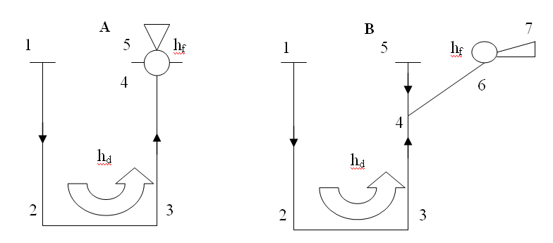
ideal mine scheme (pic.1A).
This scheme doesnít contain ways of outside air leakage
and main ventilation system channels. Thus, one can consider that Bernoulliís
equation (1) for conventional mine scheme canít be applied in real system.
hf Ī - hd= hcĪ hvs (1)
where, hf Ė fan depression, hd Ė natural air draught depression; hc Ė
depression losses on dynamic compression formation while the air is going into
the atmosphere; hvsĖ depression losses on the air shift in the ventilation
system.

–ic. 1 Simplified schemes of ventilation in a mine: ņ Ė with a fan, placed in the mouth of a shaft; ¬ Ė with a fan channel.
Thus, the application of equation (2) for air dynamic resistance
calculation of the real (main) ventilation system is incorrect because of Rvs
quantity (value) which is activated resistance of main ventilation system.
Rvs=(hfĪhd)/Q2vs (2)
Along with this equation is applied for calculations of
aerodynamic parameters of ventilation systems under conditions of real mines. It
is clear that both resistance of MVF system (net) and mine net (system) is
calculated with the regard for natural air draught effect, i.e. its effect is
taken into account twice. In this connection itís necessary to point out that
ventilation system, which is close to real conditions,(pic.1B) natural air
draught effect must be taken into account only when one calculates aerodynamic
resistance of mine ventilation system (Rm) calculations can be made by using the
following formula:
Rm=(hmĪhd)/Q2m (3)
hmĖ fan depression accounting for mine ventilation system
(net);
hd Ė depression of natural air-draught of mine;
QmĖ expenditure for air in a mine.
Aerodynamic resistance of the given system (net) (Rs.m)
must be calculated as a sum of resistance (4): of parallel connection 1(5)Ė5

Ra.l.Ė outer inleakage of air losses.
Activated resistance in MVF system (net) equals:
Rs.v=
hf/Qf2 (5)
Qf Ė fan giving of main ventilation.
Therefore, we can assert that when one calculate aerodynamic parameters of modern deep mines itís necessary to take into account their real conditions, i.e. effect of one or more MVF and natural air draught in separate ventilation profiles. So, if there are several sources of draught (MVF system and natural air draught) in the ventilation system on can say that resistance of such a system is considered to be activated, that is formed not only by aerodynamic resistance of mine extraction but with the help of different draught sources interaction.
Misunderstanding of differences between ventilation system of a mine and MVF system leads to distortion of overview of natural air draught effect after halt of MVF [1,2,3].
Letís consider simplified mine scheme as an example. (pic.1 A). Letís assume that effect of natural air draught equals to one of the dotted source of draught which depression doesnít depend on quantity of air expense in the system. To put this another way characteristic of this draught source can be viewed as a straight line that is parallel to abscissa axle.
Such a draught source of the system can be placed in inclined mine excavations where natural draught is formed.
After halt of MVF the scheme of ventilation connections is changed. (pic. 2). It must be built relatively to natural draught, as it is a dotted source that works in mine shafts.

Pic. 2. Scheme of ventilation connections of mine after halt of the fan.
In this special case it doesnít matter in what shaft the draught source is placed because in the simplified scheme of ventilation shafts (1-2, 3-4) and mine net (2-3) represent consecutive connection, and mouth of the shaft (4-5) and channel with inactive fan (4-6-7)- represent parallel connection that was linked consecutively with the rest of the system.
In such schemes of ventilation connections depression of natural air draught is allotted in proportions according to resistance of system sections which are linked consecutively. Air expense in this system (Qd) can be calculated using the following formula (1):

Ri - resistance of shafts which are connected consecutively with the rest of mine system(1-2-3-4); Rj - resistance of parallel connection out of branches which make mouth of the shaft (4-5) and a channel with inactive fan (4-6-7).
Under conditions of a real mine one can estimate quantity of expense of air coming into the mine (when MVF is stopped) only after calculating aerodynamic resistance of parallel connection, consisting of shaft mouth (4-5) and fan plant (4-6-7). To calculate resistance of shaft mouth (Rs.m) and fan which was stopped (Rf)itís necessary to measure air expense in the shaft where the fan was stopped (while the others work in REVERSE position), air expense in the channel and depression of fan plant with the fan that was stopped. (or depression measured through shaft mouth with the fan that was stopped). At the same time itís possible to estimate intensity of mineís ventilation at the expense of natural air draught when MVF was stopped. In order to do this itís necessary to do the above mentioned measurements after the reduction of mouth shaft resistance (itís necessary to open sluice box doors in the shaft building which is above the surface of a mine or open atmospheric trap door) when the fan is stopped.
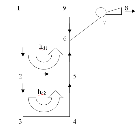
In real mines conditions of natural air draught forming can be significantly different from the ones that have been mentioned above. First of all, it can be referred to the shafts which have intermediate horizons scheme of mine ventilation with positive natural air draught can be viewed as follows. (pic.3).

Pic. 3. Simplified scheme of mine with two horizons (levels)
Ventilation air draught is formed in two ventilation profiles including shafts 1-2-5-6 and 2-3-4-5. Sections 4-5 and 5-6 or 1-2 and 2-3 are considered as ones where natural air draught will be placed. If MVF is stopped, the scheme of ventilation connections is transformed and it can be viewed as follows (pic.4)

Pic.4. Scheme of mine ventilation connections with intermediate horizon and the fan which is stopped.
Generally speaking this ventilation scheme is a consecutive and parallel connection with two air draught sources. (hd.s.1, hd.s.2). The main feature of these sources is a line characteristic which is parallel to abscissa axle. In 1-2-5-6 profile, air draught source (hd.s.1) is placed in the branch which is (1-2 or 5-6) the shaft section, but in 2-3-4-5 profile air draught source (hd.s.2) is placed in the branch of parallel connection (a dotted air draught source in the (2-3 or 5-6) shaft section. Such placement of dotted air draught sources modeling effect of profile natural air draught can be considered as the methodology of natural air draught effect modeling in parallel and consecutive connection of mine ventilation system. Calculation of air allocation in such a connection can be done with the help of the given characteristic.
Deductions
- Peculiarities of Bernoulliís equation for calculating of ventilation of open ventilation profile are considered.
- Peculiarities of calculation of aerodynamic and activated ventilation system resistance are pointed out.
- Conditions allowing to estimate the operation of natural air draught in mine ventilation system when the MVF is both active and inactive are defined.
- Methodological bases of natural air draught modeling in mine ventilation system are given.
Literature:
1. Trofimov V.A.,Zyukow Y.Y.,Kharkovoi M.V. Natural air draugh
effect on elementary profile ventilation.(Mine rescue activity:scientific
projecys collection,SRIMR D,-2003.-p.133-138).
2. Mine
Ventilation Reference book (Ushakov) Ė Moscow: Nyedra 1988.Ė
440p.
3. K. Z. Ushakow and others. Aerology in Coal Mining
Enterprises. Ė M.: Nyedra, 1987-421p.
4. Skochinski A.A. Komarow
V B. Mine Ventilation.Ė M.: Uglyetehizdat,1951.-563p.
© DonNTU 2010 Dachkovskaya Victoria


