Источник: Deutsches GeoForschungsZentrum GFZ
Introduction
Overcoring stress analysis (Leeman 1964) belongs to the borehole relief methods (Amadei and Stephansson 1997) and is used for estimating the complete in-situ three-dimensional stress tensor. The main idea behind relief techniques is to isolate partially or wholly a rock sample from the stress field in the surrounding rock mass and monitor its re-equilibrium deformation response. To convert measured strain values to stress requires information of the rock Young’s modulus and Poisson’s ratio. Details on the different overcoring methods can be found in Amadei and Stephansson (1997), Sjoberg et al. (2003), and Hakala et al. (2003). Overcoring measurements are common in civil and mining engineering and conducted for design and control of underground openings. The quality of the measurement depends on how the technical problems like drilling, gluing, overcoring are solved and how good the rock characteristics such as anisotropy, discontinuities, and heterogeneity are known (Hakala et al. 2003). Due to technical reasons the measurements are in most cases close to free surfaces (e.g., ground surface, tunnel wall) and are therefore influenced by topography, weathering and excavation activities. However, in most cases the measurements are carried out to gain information on the local state of stress and not for determining the regional tectonic stress field. Therefore, overcoring data are not extensively collected in the WSM database. There are many variations of overcoring measurements. Borehole relief methods can be subdivided into strain measurements in the borehole wall of shallow holes (e.g., CSIR (Leeman & Hayes 1966)) and strain measurements in deep boreholes (e.g., USBM (Merrill 1967), CSIRO HI cell (Worotnicki & Walton 1976)). Overcoring strains can be measured at the flat end of the borehole (e.g., Leeman 1971), at the hemi-spherical end of the borehole (e.g., Sugawara et al. 1986), as well as at the conical end of the borehole (e.g., Kobayashi et al. 1997, Sugawara & Obara 1995). All strain cells allow determining the 3D state of stress from one single measurement. Deep doorstopper gauge systems (e.g. Thompson et al. 1997, Thompson & Martino 2000) allow overcoring measurements at depth as great as 1200 m. Today, on a regular basis in underground projects pilot hole drilling followed by overcoring is used. Then, the doorstopper is the next most used technique, mainly performed in highly stressed rock when the fracturing is too intense to allow pilot hole drilling (Ljunggren et al. 2003).
General description of the overcoring technique
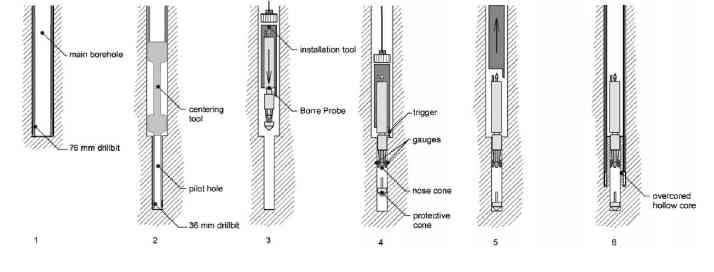
Overcoring involves installing a strain-measuring instrument bonded at the bottom of a borehole, or in a small-diameter pilot borehole drilled concentrically at the base of a larger hole. The instrument or cell is then overcored using a larger coring bit, which effectively relieves the stress acting on the hollow rock cylinder (Fig. 1). The induced strains are measured by the strain cell before, during, and after overcoring (Fig. 2). The strain difference are used to back-calculate the stresses acting on the rock cylinder prior to overcoring assuming continuous, homogeneous, isotropic, and linear-elastic rock behaviour. This needs the knowledge of the elastic properties of the rock (Young's modulus and Poisson's ratio), usually determined by biaxial pressure tests on the overcored rock cylinder on-site. Depending on the strain- measuring instrument, either the stresses in the two-dimensional plane orthogonal to the borehole axis, or the complete three-dimensional stress tensor (magnitudes and orientations) at the borehole wall, can then be determined. Additional to the strain data and rock properties following information are also needed for the interpretation: strain cell temperature while overcoring, water temperature (inflow and outflow), data logger temperature, drill water pressure, drill rotation speed, drill thrust, drill torque, depth of drilling, distance to the next free surface (tunnel, cavern, stope, shaft, borehole, quarry, slope), and distance to tectonic structures. Temperature changes to the rock or strain cell during overcoring have adverse effects on results and therefore it is important to minimize temperature variations (Martino et al. 1997).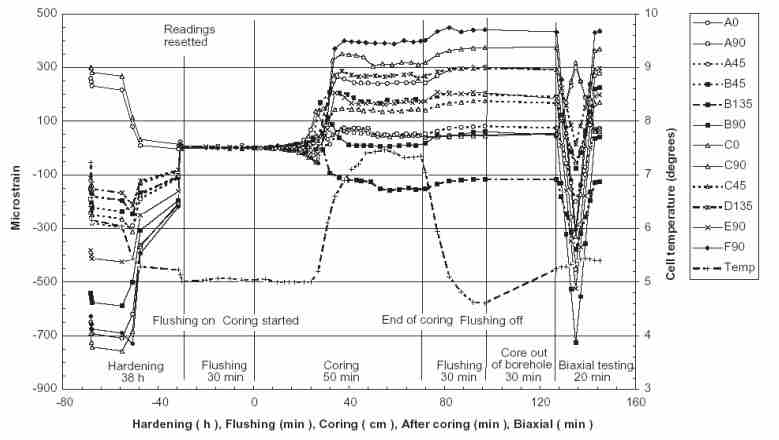
Evaluation of rock stress by means of overcoring techniques requires the assumption of ideal rock behaviour: continuous, homogeneous, isotropic, and linear-elastic. Unfortunately these conditions are seldom met completely in rock masses causing errors (accuracy). Even when ideal conditions are met, some scattering of the results always occurs (precision). Amadei and Stephansson (1997) reviewed several studies and found that the expected variability is at least 10-20 %, even in ideal rock conditions. For stress magnitudes an absolute imprecision of at least 1-2 MPa, regardless of stress component or measured value, and an additional relative variability of at least 10 % is reported for overcoring data using the Borre probe (Sjoberg et al. 2003). The variation in orientation is large, particularly for cases when two of the principal stresses are similar in magnitude, usually larger then ±15°. Different rock structures can affect in-situ stresses at different scales (Amadei and Stephansson 1997). In particular, inclusion of anisotropy due to microcracks associated with unloading of the rock has to be taken into account when analyzing stress measurements at great depth. Rock quality is a major factor when measuring in-situ stresses and large intrinsic errors can be created if the anisotropy is not taken into account. Large structures such as faults can act as in-situ stress domain boundaries and both stress magnitude and orientation can change while crossing those boundaries (Amadei and Stephansson 1997). The rock volume involved in stress measurements defines the scale of the stress state estimated. With low specimen volumes (e.g. overcoring), the absence and presence of defects is highly variable and stress values can be very different from point to point. As the specimen volume is increased (e.g. borehole breakouts, fault plane solution), the sample of defects becomes more and more statistically representative, until the representative elementary volume (REV) is reached. The REV concept applies to all rock properties, and conditions which are affected by defects, and is especially pertinent for stress data. According to Hudson and Harrison (2000), REV is defined as a volume of rock for which the size of the sample tested contains a sufficient number of defects for the “average” value of stress to be reasonably consistent with repeating testing. The far-field in situ stress (super-REV stress) is the one which we would require for the tectonic stress field. In the design of underground excavation, however, a local near-field structural stress value due to defects acting on small rock volumes (sub- REV stress) may be critical for the stability of the structure as a whole, and worth to measure. For regional tectonic stresses Zoback and Zoback (1991) claim a variety of non-tectonic processes affecting in-situ stresses near Earth's surface to dominate stress data from overcoring measurements. Because it is very hard to proof the tectonic origin of the measured stress, overcoring data in depths less than 100 m are not believed to be reliably indicative of the regional stress field at midcrustal depths. Therefore, shallow overcoring stress data are given a comparably low quality even if the quality of the measurement itself is exellent.