
|
| Resume |
| Abstract |
| DonNTU |
| Master's portal of DonNTU |

Kotelevets Alexander Faculty of mechanical engineering and engineering The department of mechanical equipment of ferrous metallurgy Specialty "Metallurgical equipment" Scientific leader proff., Eronko Sergey "Studies on physical model of dispensingshlakotvirnoi mixture into the mold of the CCM in a stream of inert gas, the definition of energy-power parameters of the design and development of an autonomous system for its implementation" Abstract Contents: Introduction Introduction The implementation of modern technology of continuous casting of steel at high casting machines involves the use of slag-forming mixtures fed to the crystallizer in order to stabilize the work of its mechanism of swing and improve the formation of brown cast ingot [1, 2]. Specified circumstances, as well as the need to reduce the number of attendants at the filling site of a new generation of CCM predetermined start of work on creation of artificial feeding and insulating slag-forming mixtures in the mold on the metal mirror with a flow rate corresponding to the rate of withdrawal of the workpiece. In most cases, a given mass flow of materials introduced into the powder or granular form, provided with moving along the mold screw feeder, which drives through frequency converters supply current can smoothly change the speed and the metering system Flow rate [3 - 5]. Appointment of the projected machine As is known, a device for dispensing material capable of continuous or discrete mode. With continuous feeding can achieve a more accurate dosing and to ensure uniform feed material with adjustable flow. These conditions feed of granular mixtures in the molds can be successfully realized with the use of screw feeders, well proven in the production of slab pieces [6, 7]. However, the relative awkwardness of a screw feeder and the need for its location in close proximity of the metal cause serious difficulties in applying such a dispensing system for high-grade caster tundish which is currently equipped with a set of devices that provide stabilization of speed limits and safety of the casting process (the locking mechanism, and the devices quickly change the dosing cup and an emergency closure of the creek). Because of the shortage of free space on the jobsite of the CCM in the zone of mold, over which there is a trolley with a tundish equipped with an appropriate amount of the aforementioned devices, the need for new technical solutions related to organization of transportation of slag-forming mixtures at a distance of 10-15 m from the power hopper to the point of entry. Analysis of existing designs Since employees' ToksSoft "aerodozator developed, including a set of metering feeders in a stream of carrier gas in the mold 4-strand CCM granulated slag-forming mixture with a particle size of 5 mm. The operating principle of such a dispenser based on the property to acquire properties of granular material flowing in contact with him in the air flow. According to the developer, the intensity of the material given design parameters and dosage can be adjusted within narrow limits, ie It is intended strictly for personal use in strict reference to the particular filling system. To enable a smooth flow control of slag-forming mixture in a wide range depending on the speed of drawing blanks on the CCM, the department faculty "Mechanical equipment of the steel mills" DonNTU a construction pneumomechanical dispenser, which was to organically combine the advantages of screw and metering aeration systems. A constructive study of the system developed Dosing scheme, developed in the Donetsk National Technical University, is shown in Fig. 1.
Figure 1 - Structural diagram of the developed feeder It includes a hermetically sealed bunker, mounted on the trolley 2 and containing a specified amount of slag-forming mixture. Dosage giving a mixture of conveying conduit 3 by means of a feeder 4, mounted inside the tank and consisting of drive motor 5 dc worm gear 6, the output shaft by means of the coupling 7 is related to shank vertical shaft 8 with the bearing supports 9 and carrying on the lower end of auger 10. Part of turns the screw is in the bunker, and the rest - in the adjacent mixing chamber 11, connected to a transporting pipeline. In order to ensure the autonomy of the dosing system is equipped with a radial fan 12, are given simultaneously in the air conveying pipe and the hopper into the cavity to create pressure to improve the issuance of the granular material into the mixing chamber. Pneumatic system also includes valves to manage the flow of air supplied to the pipeline and the cavity of the hopper. Transporting pipeline consists of a fixed (initial) part and a flexible hose at the end of which secured a special pipe to distribute the mixture on the surface of the metal in the mold. The proposed dosing system combined type not only provides high stability space, and hence the mass flow of material, but also the broad scope of its changes as by adjusting the frequency of screw rotation, and because of the throttling jet transporting air. Method of calculating the dosing system Design industrial design of the proposed system required the development of methods to calculate it. Performance dosing was determined taking into account the specific consumption of slag-forming mixture, which process conditions for casting metal casters is 0,3 - 0,5 kg / t of steel [8]. Mass flow rate of steel (m / min) in a continuous casting:
Required mass productivity (kg / min) of each of the two feeders:
We express the mass productivity of the screw feeder through the geometric and velocity parameters, taking into account bulk density fed them a mixture of
Outer diameter of the coil screw will be:
Substituting in the formula for given values ??of bulk density of the slag mixture dosage and frequency of screw rotation, define the outer diameter of its turns, and then from the above relations - the other key dimensions that are needed to calculate the energy-power parameters drive dosing. In developing a refined method for calculating the proposed delivery system of slag-forming mixture used previously obtained information about the characteristics of a vertical screw feeder [9, 10], as well as basic theoretical positions to determine its structural characteristics [11]. Consider a continuous odnozahodny vertical screw with a constant step S, the outer radius R and radius shaft r. In accordance with the scheme shown in Fig. 2, the time, which prevents the rotation of the screw, due to the resistance to move (push) the material flow, filling the spiral channel formed by the turns of the screw and shaft, as well as covering the coils of the cylindrical surface. And this is cylindrical surface at the site fence turns the screw is formed of loose materials, and below them - the walls of the guide sleeve.
Figure 2 - Arrangement of slag-forming mixture on coils vertical auger Aspect ratio of the screw should be such that the bulk material flowing out of the bunker into the gap between the turns and the edge of sleeve, was held on the surface of the fixed screw auger, a limited sleeve. In this case, this surface forms a slope at an angle to the horizontal. Length of horizontal projection of L sweep the helix, as well as the number of turns the screw in the sleeve, needed to hold the material on the surface turns to be greater at the same step, the screw S, the greater the angle of the coil and the smaller the angle of repose of the dosed material.
Upon receipt of the theoretical dependence, which allows to calculate the moment of resistance, acting on a rotating vertical auger dosing unit, were taken into account the following conclusions on the results of laboratory tests:
From the circuit shown in Figure 2,
At the time of start-up drive dispenser of granular material under the influence of foreign forces from the screw removed from a state of rest. Initial momentum, causing the movement of bulk material to the upper coils of the screw, located above the outlet of the hopper, a pressure gradient arising in the instantaneous formation of voids inside the material at Breakloose from the place of the working body. Turns of the screw pull from it the amount of particles in the form of a cylinder which is in interturn space and tell them to move on the complicated trajectory close to the helix. In the formed cavity of the environment under the action of lateral pressure rush surrounding the particle material, releasing dipping particles from upstream layers of granular material, resulting in a like pole of the moving bulk cylinder, and on the free surface there is an annular groove. Period of unsteady flow in a screw filler is a short-lived and after a 1-2 with the motion becomes stable with constant values ??of the average axial and the absolute angular velocity. In this case, a 100% filling material dosed interturn space auger and the lack of slope on the surface of the screw.
Dividing both sides of this expression for S, we obtain the number of turns of the screw in the guide sleeve, which ensured retention of the material on the entire surface of the screw:
Moment of resistance, acting on a rotating screw, due to the presence of forces that impede the movement of material flow in a helical channel formed surface screw and cylindrical surfaces of the vertical channel in the thickness of the granular material in the suction side of the bunker, as well as the guide sleeve. At the bottom of the helical channel formed by a kind of wedge, latching promotion following it layers of material in the guide sleeve, resulting in his seal and as a consequence of sharply increasing the pressure on the inner surface of the cylindrical wall of the sleeve and on the surface of the screw. On the figure 3 shows the calculation scheme for determining the values ??of moment of resistance, acting on the screw when dispensing the material.
Figure 3 - Estimated scheme for determining when resistance to rotation of vertical screw In accordance with this scheme the length of the screw channel, which forms a wedge:
To plot a helical channel, concluded between the surface of the screw and the guide sleeve, within which there is 100% filled space interturn material:
The length of the screw channel in the suction side of the bunker
The force required to move the wedge down:
The force of gravity of the material:
The force of friction of loose bodies in a volume of the wedge, the side walls of the channel:
Lateral pressure of slag-forming mixture on the walls of the channel:
Lateral surface area of ??the wedge:
After substituting in the original formula for the values ??of performing mathematical transformations we obtain the expression:
Axial pressure at the section 1-1 (Figure 3) needed to shift the wedge down:
Cross-sectional area of ??screw channel:
Axial pressure in the granular body at a distance x from the section 1.1, provided the equilibrium thickness of the selected element dx:
Elementary force of friction:
Girth screw channel:
After integration, we obtain
Then, the axial pressure at the section 2-2:
Hydraulic radius of cross section of the channel:
The exact boundary of the zone began packing material is unknown. Therefore, accept the assumption that the beginning of this zone is located at the intersection of the upper edge of the guide sleeve to the middle height of the channel. Then, in accordance with the scheme shown in Fig. 3,
Hence,
From the equilibrium condition of loose bodies in the channel:
The force of friction material on the sidewalls of the channel:
Part of the perimeter of the cross-section of the channel formed by the surfaces of the turns and the screw shaft:
Part of the perimeter of the cross-section of the channel, related to the surface of loose material, adjacent to the surface of the roaming screw loose body:
Axial pressure at the section 3-3:
We transform:
Therefore, the second term can be neglected. Then
Pressure caused by the circumferential force:
Circumferential stress on the screw:
Resisting moment acting on the screw:
Power of electric motor used in the drive dosage is determined by the formula:
The total gear reduction gearing driving the dosing system:
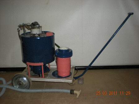
Pilot sample dosing system Using the obtained dependence of the calculated, designed and built a pilot sample dosing system (photo in Fig. 4).
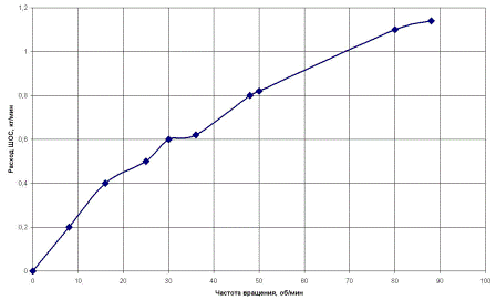
Figure 4 - Experimental design pneumatic mechanical system dosed injection of the slag-forming mixture into the mold of the CCM During testing of the proposed metering system to exercise control mass flow of granular mixtures issued from bunkers at different rotational speed of the vertical auger. The data obtained have constructed feeder discharge characteristics, the graph is shown in Fig. 5. In accordance with the amount of material fed to the screw is directly proportional to the frequency of its rotation, thus ensuring a smooth adjustment of operating conditions consumption of slag-forming mixture flowing into the mold caster. The results of visual monitoring and analysis of video streams gaspowder mixture flowing into the model of the mold for billets of circular cross section, showed that the dosing system provides a stable mode of transportation of granular material and its uniform distribution over the surface between the walls of the protective glass and metal reservoir (photo in Figure 6 ). The maximum distance that may be filed powdered slag-forming mixture with the proposed dosing system is determined by grading the material, as well as pressure and flow rate transporting air from a centrifugal fan.
Figure 5 - Schedule of expenditure characteristics of the metering system, built according to experimental data
Figure 6 - The distribution of the cross section model of the mold of granular material fed into the conveying air stream Conclusion Thus, the results of theoretical and experimental means for studying the system dosed injection of the slag-forming mixture into the mold of the CCM, in good agreement that allows us to recommend the method of calculation of its energy-power parameters for practical applications in engineering design offices of organizations involved in the development of devices class.
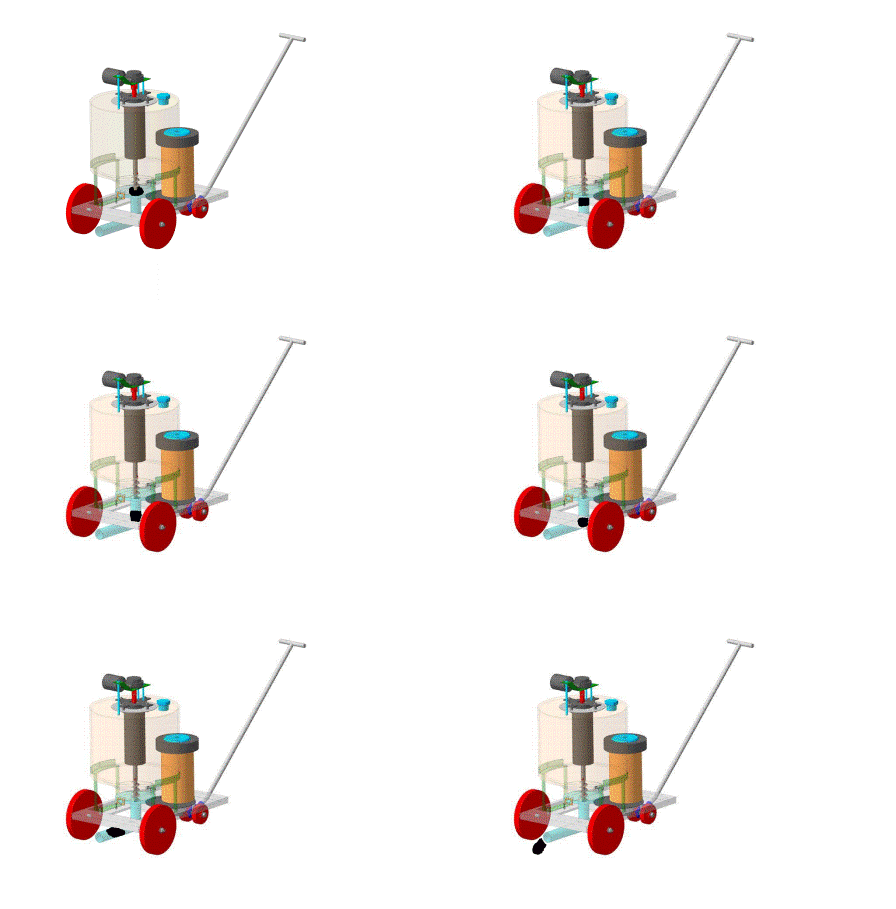
Figure 7 - The animated image of the principle of aerodozatora (150 KB, 10 images, 7 cycles of repetition) References
Important note In writing this essay master's work is not completed yet. Final completion in December 2011. Full text of the work and materials on the subject can be obtained from the author A. Kotelevets, or its leader, S. Eronko, after this date. Resume |


