
Source of information: http://kopflex.com/EPTroot/public/KopFlex_tech_papers/MMC8.PDF
The useful life of a gear-type coupling is limited by the rate of wear of its teeth. This wear rate is heavily influenced by lubrication and the type of wear that occurs. Here are some facts that may help you avoid coupling failures on critical rotating machinery trains
GEAR COUPLINGS are called "gear" couplings because they transmit power from one shaft to another through members incorporating involute profile teeth. The similarity between gears and gear couplings stops there. Gear couplings are more like splines than gears; but contrary to splines, couplings are designed with relatively large pitch diameter, short tooth length and large backlash. For couplings:
The speed ratio is always unity.
The input and output shafts are in substantially coaxial alignment.
The gear mesh does not change; each tooth contacts only the same corresponding tooth.
The relative motion between the teeth is in the axial direction.
Because they differ functionally from gears, gear couplings have their own particular ways of wearing and they have lubrication problems not encountered in gears. A few of these particularities form the subject of this article.
Fig. 1 represents half a gear coupling in an angularly misaligned condition. The relative position of all the teeth is also shown. This illustration shows that the relative motion is composed of an oscillatory axial motion and of a rocking motion. The velocity of the oscillatory motion has a maximum value which is defined by:
Vs = ? • ? • R
where, Vs = maximum sliding velocity (in./sec.);
? = angular velocity (rad./sec.);
? = angle of misalignment (radius);
R = pitch radius (in.).
and is generally known as the sliding velocity. The following numerical examples will give the reader an idea of the order of magnitude of sliding velocities;
• High speed couplings: 10,000 rpm; 2 minutes misalignment; R = 3 in., Vs = 1.8 in./sec.

Fig. 1 — Developed plan of an angularly misaligned gear coupling
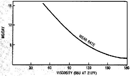
Fig. 2 — Effect of lubricant viscosity on coupling wear
• Standard couplings: 1,800 rpm; 20 minutes misalignment; R — 3 in., Vs = 3.3 in./sec.
• Spindle couplings: 900 rpm; 3 degrees misalignment; R — 3 in., Vs = 15 in./sec.
The sliding motion is the main cause of coupling wear or failure. Limits for the sliding velocity are found in the literature,2 and are used by coupling manufacturers in establishing ratings. The rocking motion, on the other hand, is the motion that helps in lubricating the teeth and, as such, is a desirable feature. The angle of the rocking motion is equal to the angle of misalignment, and is independent of speed. This rocking motion is the reason why spindle couplings can work satisfactorily at large sliding velocities, but high speed couplings can fail even at reduced velocities. Because the rocking motion in-fluences the lubrication, the sliding velocity should not be used solely as a criterion for the coupling's operating conditions.

Fig. 3 — Coupling condition during break-in
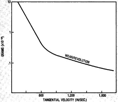
Fig. 4 — Effect of pitch line velocity on coupling wear

Fig. 5 — Wear rates of a gear coupling as a function of speed
Gear couplings need lubrication in order to prevent the rapid wear that could be generated by the forces normal to the teeth and by the sliding motion. The two most common methods of lubrication are batch and continuous flow. In the batch method, the couplings are filled at installation with either oil or grease. The coupling (for batch lubrication) incorporates a seal which has the double role of retaining the lubricant and preventing the entrance of contaminants. In time, the lubricant either deteriorates or leaks out, so that this type of coupling requires periodic relubrication. Continuous lubrication has several advantages. It cools the coupling and, therefore, permits operation in a hot environment. Also, the coupling and the connected machinery may be tied to the same lubricating system. With this type of coupling lubrication, however, precautions must be taken to keep the contaminants in the lubricant from accumulating around the coupling teeth under centrifugal action.3
Under proper operating conditions and good lubrication, gear couplings can perform satisfac-torily for many years. A good hydrodynamic lubricant film is unlikely to be generated by the oscillatory motion of small amplitude which exists in most gear couplings. However, the relatively high centrifugal forces insure a complete immersion of the teeth in the lubricant. Under improper operating or lubricating conditions, the wear is adhesive, and the coupling becomes inoperative in a relatively short time.
The viscosity of the lubricant has a substantial influence on the wear-rate, particularly at low and moderate speeds. For many years it was held that a high viscosity is desirable.4 A study of the influence of lubricant viscosity on coupling wear-rate was recently conducted by the author. The results shown in Fig. 2 illustrate that a high viscosity lubricant can substantially reduce the wear-rate. One exception is discussed later. Wear can influence the coupling's performance in two ways:
As the tooth thickness is reduced by wear, its beam strength is decreased. The safety factor used in design allows the coupling to continue to transmit the torque even with thinner teeth. However, under unusually poor operating or lubricating conditions, the teeth can become so thin that total failure occurs.
Many gear coupling designs use the tips of the hub teeth to pilot the floating member. When the coupling operates at high speed, it must be dynamically balanced, and for proper balancing the accuracy of piloting the floating member is critical. Under normal conditions, the tips of the hub teeth do not wear, because the centrifugal forces in the sleeve create a very small clearance between the hub tooth tips and the sleeve. However, if contaminants, particularly water, are allowed to enter the coupling, they can corrode the tips of the hub teeth and, thus, increase the clearance. The resulting increase in unbalance can require replacement of the coupling, even though its torque transmitting capability was not impaired.
Wear-rate is relatively high during the breaking-in period of any coupling. Depending on the precision of manufacture, not all the teeth participate equally in the transmission of the torque during the first hours of operation; hence, the tooth pressure is not uniform around the pitch circle. The teeth having highest surface pressure tend to wear faster than the rest. As these teeth wear, the other teeth transmit more of the torque, and the over-all wear-rate gradually decreases. Eventually all teeth transmit the torque equally and the wear-rate becomes constant. Fig. 3 represents the variation in wear and operating temperature during the first days of operation of a gear coupling having non-heat treated carbon steel components.
The completion of the breaking-in period can be easily observed. For couplings with hardened tooth surfaces, the duration of breaking-in is longer, and higher initial temperatures can be ob-served. This is due, both to the better wear resistant surfaces and to the distortions which generally occur during the heat treatment, and which further reduce the number of teeth initially in contact. In addition to surface hardness and misalignment, coupling speed has a significant influence on wear-rate. Fig. 4 shows the relationship between the wear per revolution and linear velocity at the pitch diameter. The same graph was reduced to wear-rate as a function of rpm, for one particular coupling as shown in Fig. 5. It can be seen that couplings will last longer as rotating speed is increased.
Gear coupling manufacturers and many oil companies recommend that when grease is used for lubrication a soft grease be used at low speeds and a stiffer grease at high speeds. Sometimes, however, a maintenance mechanic will use a stiff grease in a coupling running at low speed, with rapid wear as a consequence. In order to determine, more precisely, when to change from a stiff to a soft grease, a study was conducted in which couplings of various sizes were lubricated with stiff greases and run at gradually decreasing speeds. Below a given speed the wear-rate changed drastically, and rapid failure of the couplings occurred. The appearance of a coupling tooth which failed under these conditions is shown in Fig. 6. An empirical formula was developed, which gives the minimum speed at which a coupling lubricated with a stiff grease (penetration factor smaller than 310) can operate and not suffer this type of rapid wear.

where, N = Coupling speed (rpm)
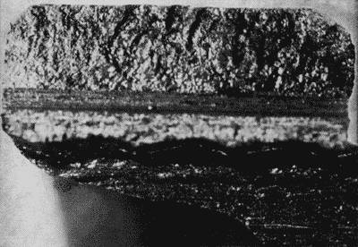
Fig. 6 — Tooth failure caused by operating a coupling lubricated with stiff grease at too low a speed
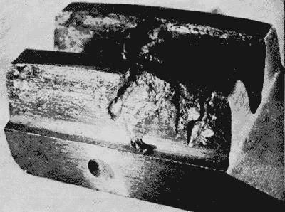
Fig. 7 — "Worm track" failure

Fig. 8 — "Worm track" failures on mating parts
It was found, experimentally, that rapid failures at low speeds are independent of torque, misalignment and tooth geometry, but the wearing process can be retarded by hardening of the teeth. It was also found that this type of failure is very rapid when the grease used has more than 8 percent soap content.
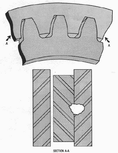
Fig. 9 — Schematic illustrating congruency of "worm track" failures
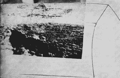
Fig. 10 — Metal chip adhering to tooth tip
For many years, a particular type of tooth surface damage puzzled coupling users. Because of the strange ap¬pearance of the damage, this type of wear is known as "worm-tracks." Fig. 7 illustrates a coupling tooth with worm-tracks. The problem was extensively studied by the U.S. Navy,5 and it was concluded that "failure by worm tracking occurred when the sliding velocity fell in the range of 5 to 8 ips."
The same report also states: "Examination of the failed couplings revealed worm tracking to be the result of metal fatigue; the exact mechanism involved is still somewhat of a mystery." Our evaluation of couplings damaged in service, and our laboratory experiments, have shed some light on the mechanism of worm tracking.
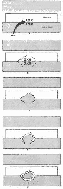
Fig. 11 — Mechanism of "worm track" formation.

Fig. 12 — A section through a "hump."
The first striking fact observed in analyzing a number of failed couplings was that the worm tracks are always perpendicular to the direction of relative motion, and that they always appear on both mating surfaces of the sleeve and hub teeth. These worm tracks are congruent, is illustrated in Fig. 8, and sketched in Fig. 9. The void at the worm tracks was not gradually worn away, rather it was formed by displacing large pieces of metal. Fig. 10 illustrates such a chunk of metal, laminated to the tip of one tooth.
The mechanism of worm track formation is shown sequentially in Fig. 11. Sequence "a" shows that two mating teeth become welded at the interface. It has not been determined what causes this welding, but it is probably due to a combination of improper lubrication and misalignment conditions.
The localized high temperatures which generated the welding are evidenced by the discoloration of the teeth. The weld severely restrains the motion between the cou¬pling's parts which, in turn, causes vibration in the sys¬tem. Simulated tests have demonstrated this occurrence, and short duration welding has been monitored through acoustical, temperature and friction measurements, as well as electrical resistance measurements between the teeth.1
Under this unusual condition, high shear forces are generated in the weld. As a consequence, superficial cracks appear on the teeth (sequence "b") and on one tooth or the other, the cracks eventually meet as shown in sequence "c." A piece from one tooth is, hence, trans-fered to the other, having the appearance of a "hump." A section made through a "hump" is illustrated in Fig. 12. The superficial cracks and the weld zone can be easily observed. This hump still pre-vents the relative movement between the teeth, and it is subjected to a rapid ham¬mering on both sides. Three things can then happen:
Under certain conditions, the hump is literally extruded from between the teeth, as illustrated in Fig. 7.
If the cracks under the hump are deep enough, the hump is freed from the tooth, as shown in sequences "d" and "e" of Fig. 11. Sequence "d" is also illustrated in Fig. 13. Under the effect of centrifugal forces, the freed piece of metal works its way out radially and, in this case, the worm track extends to the tip of the hub tooth.

Fig. 13 — A particle trapped in a wear scar
It is also possible that the freed piece of metal remains between the teeth until the coupling is taken apart.
All of the worm tracked couplings that the author has observed confirm this mechanism of formation. Work has been done in our laboratory to determine the con¬ditions which generate the formation of worm tracks. In the experiments performed to date, we obtain worm tracks only when the lubrication conditions are inten¬tionally degraded.
Speed has a significant influence on coupling wear: high speeds reduce the wear-rate; while low speeds can, with some lubricants, cause the coupling's failure. We can only conclude that increased rotating speed helps in improving the lubrication conditions. Worm tracks are caused by very localized welding and, as such, the sliding velocity alone cannot be blamed for this type of failure. It is likely that worm tracks are caused by a combina¬tion of unfavorable torques, misalignments and sliding velocities. Because little can be done about the torque, and because the alignment often cannot be improved, the best way to avoid reoccurrence of worm tracks is to improve the lubrication. This can be done either by sup¬plying a larger oil flow to the coupling or by using a better grade of oil.