
Technical basis for signaling circulation or removal of drilling fluid at present is not perfect enough, so these devices are used sporadically. At the same time, the use of such devices could solve the problem of controlling the circulation of drilling fluid in the borehole during drilling and early detection of takeovers to prevent sticking of drilling tools.
Thus, for the practice of drilling wells in the Donets Basin is a very urgent task of improving the technical means of monitoring the flow of drilling fluid in the borehole. This will improve the technical and economic parameters of drilling by preventing accidents.
The purpose of the work – the improvement of the concept and design of control signaling the circulation of drilling fluid in the borehole and justification of its use of technology.
Research Objectives
- Analysis of current state of well controls the circulation of drilling fluid, or acquisitions.
- Improving the concept of signaling circulating drilling fluid in the borehole.
- Numerical modeling of signaling circulation drilling fluid in the well to determine the rational design parameters under various operating conditions.
- Improving the design of signaling circulating drilling fluid in the well and the technology of its application.
Object of study – engineering controls circulating drilling fluid in the borehole.
Subject of research – work processes The indicator circulation drilling fluid in the borehole.
Description of the proposed operation principle and constructive scheme

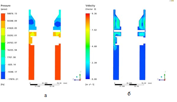
When drilling in the area of drilling fluid absorption (Fig. 2, b) due to the fact that not all of the liquid reaches the surface, the pressure on the sensor dynamic pressure is reduced to DР2. When the sensor changes its position, the hole in the signaling element is reduced, and the loss of pressure in it increases to DР2с. This rise in pressure is recorded on the manometer.
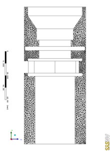
Thus, the change in pressure drop across the sensor, the velocity head can be directed signaling element. On the basis of the proposed scheme (Fig. 1) developed a structural scheme of signaling device, as shown in Fig. 2, on which the patent for utility model number 50771 from 25.06.2010g [1]. His work is shown in Fig. 3.


Similarly, signaling device triggered and the fall of liquid level in the well below its spot, because this valve 10 to completely cease to apply force from the drilling fluid in the annulus hole.

The application of this device allows you to control the absorption of drilling fluid in the borehole regardless of whether the fall of the liquid level due to changes in the resistance of fluid motion while reducing its velocity in the annulus wells at the installation switch.
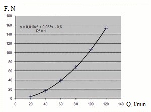
In modeling [2] determined the forces acting on the valve plate signaling device that allows you to choose a return spring valve and determine its sensitivity to changes in fluid flow.
Calculations were performed for two structures with different modes of signaling rinse well, and taking into account the rotation of the drill string without it. In this case, the simulation for different sizes of valves – sensor speed pressure. The pressure drop across the valve is calculated by numerical simulation using finite elements.
As an example, modeling that was conducted for the fluid flow rate 20-120 l / min for 93 mm diameter hole, covered with casing diameter of 89 mm with an inner diameter of 79 mm. Model on which the calculations were shown in Fig. 4. Simulation results were shown in Fig. 5
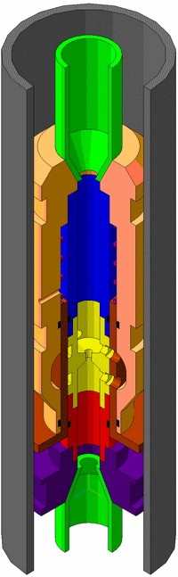
Taking into account the settlement was created a real signaling device design fluid circulation in the hole, 3-D model is made in the CAD package Compass 3D »and is shown in Fig. 7. In this model, developed design documentation for the switch.
Conclusions and future research
Proposed a refined principle of signaling and structural scheme designed to implement it.
For signaling circulation drilling fluid was simulated in the package «ANSYS» to determine the forces acting on the valve at his job. Calculations were performed for the well O93 mm with and without rotation of the drill string, with normal and elevated feeds drilling fluid and well O151 mm without rotation of the drill string. Based on these calculations, it was concluded that the rotation of the drill string does not affect the pressure loss in the switch. The results of the simulation allowed to design a switch for various drilling conditions.
Have also been proposed rational relationship of design parameters that are included in the basis of recommendations from the application of the developed sensors.
On the constructive scheme of the design signaling device circulation drilling fluid for use in wells. The design of signaling device patent of Ukraine for useful model number 50771 from 25.06.2010.
Application of the developed design signaling provides the ability to more accurately and quickly identify the absorption of drilling fluid, which prevents accidents and saves resources and money.
References
Патент України на корисну модель № 50771 МПК7 Е21В 25/00. Сигналізатор поглинання промивальної рідини в свердловині / Каракозов А. А., Парфенюк С. Н., Роль А. В., Сайгайдак И. Д., Назарян А. О. – опубл. 25.06.2010. – Бюл. №13. – 6 с., ил. Каракозов А.А., Парфенюк С.Н., Назарян А.О. Разработка сигнализатора поглощения промывочной жидкости при бурении геологоразведочных скважин / Наукові праці ДонНТУ. Серія "Гірничо-геологічна" Випуск 14(181), Донецьк, ДонНТУ – 2011, с. 252-256.