
Abstract
- Introduction
- 1. Theme urgency
- 2. Goal and tasks of the research
- 3. An approach to the unification of synthesis of Moore FSM on FPGA
- Conclusion
- References
Introduction
Nowadays replacement arthroplasty is one of the most progressive methods to treat surgically joint diseases of different etiology. It is quickly developing and becoming commonly used in the orthopedic practice. Thigh fractures in the central part is a widely spread trauma in the elderly and the frequency of traumas like this increases with the age. Therefore, this problem concerns not only orthopaedic surgeons but it is becoming a scientific and engineering problem as well.
1. HISTORY OF DEVELOPMENT OF REPLACEMENT ARTHROPLASTY IN THE WORLD AND UKRAINE
Replacement arthroplasty has been in existence for more than 70 years. The first high-technological femoral-head prostheses with an intramedullary pedicle made of vitallium (cobalt-chrome-molybdenum alloy) were the prostheses made by F.R. Trompson and A.T. Moore (Fig.1).The introduction of namely these single-pole prostheses made plastics of a femoral-head a standard surgical interference [1].
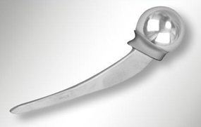
Figure 1 – Рrosthesis A.T. Moore
A complex task has been set to us: investigation of the stress –strain state of the system thigh bone – implant when there are fractures in different parts of the proximal section of a thigh bone as well as automatic selection of the optimal implant sizes for each particular case. In order to solve this task effectively it was broken into some steps:
1) 3D- model development of a thigh bone and the selection of the initial data for the following investigation step;
2) 3D- model development of an implant, implant material selection and the investigation of different plate configurations;
3) translation of a 3D- model of a thigh bone into the software system of the finite-element analysis ANSYS and the development of the model;
4) strength calculation and the analysis of various types of thigh bone fractures; the analysis of the reserves and the improvements in implant design;
5) development of technological process in Power Mill medium and the development of the flexible production module to machine a metallic plate.
2. 3D- MODEL DEVELOPMENT OF A THIGH BONE AND THE SELECTION OF THE INITIAL DATA
A thigh bone has a complex configuration and in order to obtain its 3D model a coordinate-measuring arm was used which was synchronized with a modeling package PowerSHAPE of DELCAM company.
The model which has finally been received has some geometrical differences from the real prototype but in no way it can influence the results of the strength calculation because the main task is the calculation universalization that is the creation of automatic individual approach to each patient.
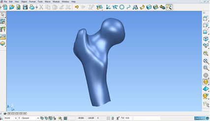
Figure 2- 3D-model of a thigh bone
3. THIGH BONE STRENGTH CALCULATION IN ANSYS MEDIUM
To carry out strength calculation it is necessary to have a 3D-model of a thigh bone in the medium of ANSYS software system. To create a calculation model in the process of its translation from DELCAM PowerSHAPE into ANSYS the configuration of the bone in some places was “averaged” to some extent, that is it was approximated to a regular-shaped object [7].
Figure 3 – 3D-model of a thigh bone
(animation: 5 frames, 7 cycles of repeating, 160 kilobytes)
To simplify calculations the material of a thigh bone was assumed to be homogeneous. When applying the load we fixed rigidly the end of the cylindrical part of the bone and applied uniformly the distributed load to the spherical part. The value of the distributed load was 6 000 Н taking into account the influence of the dynamic factor. Having done the structural analysis of the model we received the following results:
- maximum and minimum stresses (Fig.4)
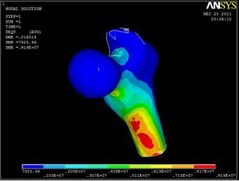
Figure 4 – Stress distribution on a thigh bone
- elastic strains (Fg. 5)
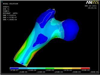
Figure 5 – Elastic strains in a thigh bone when applying the load to its spherical part.
Having done the strength calculation we defined the maximum and minimum stresses equal to 9,5 МPа and 0,8 МPа respectively. And the elastic strain did not exceed 47*10-7 m.
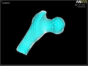
Figure 6 - A thigh bone model in ANSYS medium
Then we created a simplified 3D model in ANSYS where we showed figuratively the fracture. Then following the rule of ensuring the joint strength we investigated the stress-strain state of the system by changing the metal plane thickness and we automatically selected the necessary configuration and the thickness of the plane [4]..
The data obtained about the plate was translated into the program Power Mill, where the blank part most similar to the required plate is selected from the database of the metal plates and the control programme for the final machining of the inner part of an implant is automatically written.
CONCLUSIONS
The following problems were considered while carrying out this investigation:
1) 3D- model development of a thigh bone and the selection of the initial data for the following investigation step;
2) 3D- model development of an implant, implant material selection and the investigation of different plate configurations;
3) translation of a 3D- model of a thigh bone into the software system of the finite-element analysis ANSYS and the development of the model;
4) strength calculation and the analysis of various types of thigh bone fractures; the analysis of the reserves and the improvements in implant design;
5) development of technological process in Power Mill medium and the development of the flexible production module to machine a metallic plate.
Note:
When writing this abstract master's work is not yet completed. Final completion: December 2012. The full text of work and materials on the topic can be obtained from the author or his head after the specified date.
References
1) Helwig Р. Finite element analysis of a bone-implant system with the proximal femur nail/ Technology and Health Care 14 (2006)-p. 411-419
2) Каплан А.В. Повреждения костей и суставов. 3-е изд. М.: Медицина, 1979.- 568 с.
3) Каплун А.Б., Морозов Е.М., Олферьева М.А ANSYS в руках инженера: Практическое руководство. М.: Машиностроение, 2003. - 272с.
4) Басов К.А. ANSYS справочник пользователя. М.:ДМК Пресс, 2005. -640 с.
5) Чигарев А.В., А.С.Кравчук, А.Ф.Смалюк ANSYS для инженеров. Справочное пособие. М.:ДМК Пресс, 2003. -780 с.
6) Станочное оборудование ГПС. Справочное пособие / Е.С. Пуховский, А.Б. Кукарин, И.Л. Вовченко, Г.С. Грачев. – К.: Тэхника, 1990. – 175с.
7) Уотсон-Джонс Р. Переломы костей и повреждение суставов. М.: Медицина, 1972.- 708 с.