ABSTRACT
Here proposed the new conception of preparatory mine-workings stability providing in deep mines on account of new combined method of arched timbering hard-longitude reinforcement with cast band and the layer roofing crutching
1 INTRODUCTION
The preparatory mine-workings in deep mines are being intensively deformed in the area of second working influence. The methods of protection and timbering facilities applied do not provide their stability in the area of second working intensive influence. The production faces experience under coal layers working at greater depths is an evidence of this. The significant amounts of monetary funds and material resource are spent on repair and re-timbering of mine workings over substantial displacements of their rock contour. The methods of protection and timbering facilities presently applied do not correspond to the mine pressure manifestation features on ending areas of the drifts and this is a main reason of mine-workings unsatisfactory conditions (Jakobi 1987, Litvinsky 1999).
2 COMBINED METHODS OF STABILITY PROVIDING IN PREPARATORY MINE-WORKINGS OF DEEP MINES ANALISYS
Some mines of Donetsk region successfully use the combined method of the preparatory mineworkings maintenance in the area of the second workings influence where the crutch-arched timbering combined with hard cast bars made of cement-mineral blends are implemented. The experience of average width (1,8 - 2,2 m) coal layer working out at mines of "Krasnoarmeyskaya-Western #1" and “Zasjadko” under daily coal production of 3000-4000 tons a day per a longwall has demonstrated that the recurring use of the former conveyer drifts as ventilation supply is necessary to provide the timely preparation of new production faces. To provide this the conveyer drifts were protected with cast bars of 1.4 m in width made of cement solution "Tekland" type with mineral additives (Baysarov 2001, Baysarov 2003, Iliashov 2006). The solution was supplied by pump into the plastic shells of chemical fiber reinforced with metal netlike tie-beam and wooden timber on sides.
To provide stability of the roofing rocks there was installed a system of 13 chemical crutches of 2.9 m in length radial located on perimeter of the excavation and bent over towards the drift with angle of 10-15 degrees from vertical line. Crutches installation was carried out in 2 stages: in the beginning there were installed 5 symmetrically located crutches in tunnel face, and then there were fixed 8 additional crutches between the earlier installed ones at distance of 100-120m before production face. Moreover, lateral crutches on ending tops were installed in pairs and were jointed between themselves with curvilinear support-bars to provide the possibility of the arched timber legs removal and fixing its tops over the longwall joint to provide the conveyer drive traveling.
To estimate the working efficiency of the cast bar and to specify the parameters of its installation in layer d4, block 5, 2-d south conveyer drift (the cross-section – 15.5 sq.m, arched pliable timbering - KMP-A3) of "Krasnoarmeyskaya-Western #1" mine there were carried out an experimental-industrial check up and a comparative estimation of 4 methods of protection (Baysarov 2003). Within the first, the second and the third method the cast bar of 1.0 m in width was raised at distance of 1.0 m, 0 m and 0.5 m accordingly from the excavation edge. Within the fourth way there were raised 2 cast bars of 0.6 – 0.8 m in width at distance of 0.6 m from each other and the first bar was erected on the drift edge directly.
The analysis of the experiment results has shown (Baysarov 2003) that the fourth method manifested the minimal displacements of the roofing rocks (up to 50 mms) and of the ground (up to 100-150 mms). The roofing load on cast bars was distributed evenly. However, this variant was remarkable for its technological difficulty in execution and significant consumption of cement-mineral mixture. Thus, the third method of the cast bar installation (the displacements of the roofing - 50-70 mms, and of the ground - 150-200 mms) was the most efficient among 4 considered variants.
The cast bar implementation reduces sizes of the rock roofing destruction area, and increases contour, inter-layer and deep-laid stability of the roofing. This allows preserving the conveyer drift section for the recurring use of it as a ventilation tunnel. The excavation cross-section forms 60-80% from the designed one after completing the first drift. The cast bar using practice has revealed the cost of its installation formed 150 - 200 hrivnas per meter.
Using of the immediate roofing rocks chemical crutching is rather efficient way to provide stability of the roofing rocks in producing excavations. However, the cost of this method is rather high. At mine of "Krasnoarmeyskaya Western #1" the overall expenses for installation the system of 13 chemical crutches with a 0.8 m drift step have formed (17 + 68)·1.25·13 = 1380 hrivnas/m under the cost of 16-18 hrivnas/stick per a crutch and of 65 - 70 hrivnas/stick per its installation. Thus the expenses on this method 7-11 times exceeded the cost of the cast bar maintenance.
In our opinion, providing of the preparatory mine-workings stability in deep mines is possible while using the rational combination of new and existing efficient protection methods and facilities of the excavations maintenance in area of the second working influence. For instance, researches of mechanism of the crutches interaction with lateral rocks and of their location geometries peculiarities have allowed creating the carrying rock-crutches construction where metal rods of the chemical crutches are being used as reinforcing elements in the working roofing (Petrenko 2004, Kasyan 2006).
There was carried out an experimental-industrial check up for the efficiency of new method for hard-longitude reinforcement of arched timbered preparatory mine-workings in some Donetsk mines ("Yuzhnodonbasskaya #3", ABAKUMOVA, KALININA and SKOCHINSKOGO). It has confirmed its rather high efficiency in the area of the second workings influence.
3 HARD-LONGITUDE REINFORCEMENT OF ARCHED TIMBERING USED AT “YUZHODONBASSKAYA#3” MINE
There were used strengthening timbering of two longitudinal beams of 4.5 m long made of double tee #14 with segment of rigidity located between the beam and a top segment of arch in ventilation drift of the 4-th eastern longwall of c11 layer in "Yuzhnodonbasskaya 3" mine (fig.1) (Bondarenko 1999).
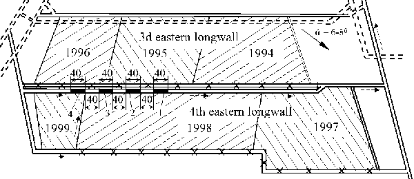
Figure 1. The mine-working plan of the 4th eastern longwall layer с11 of Yuzhnodonbasskaia #3 Mine/>
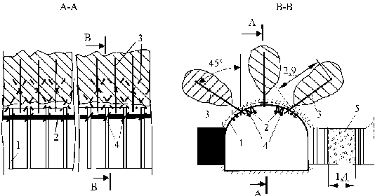
The beams were hung up to the top segment of arch with overcloak of 0.5 m with 2 special hooks with cleats and nuts. To provide the longitudinal-beamed reinforcement efficiency there were additionally installed two chemical crutches of 2.5 m long, joint with the top segment of arch and a beam with a conveyer chain segment (fig.2).
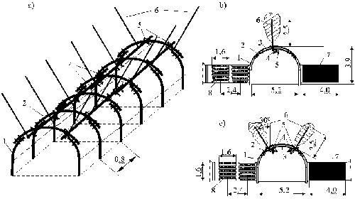
Figure 2. Longitudinal crutch-beam strengthening timbering construction: 1 - timbering leg, 2 - top segment of arch; 3 - curvilinear section of the top segment of arch (SVP-27) 4 - longitudinal beam made of double tee #14; 5 - elements of the beam hardware to the top segment of arch timbering; 6 - steel-polymeric crutches; 7 – coal pillar; 8 - cribs filled with rock
The ventilation drift, made with a coal-plough machine close to the worked out space with a coal massif remained in 4 m in width, was protected by 2 rows of wooden supports of 1.6х1.6 m filled in with rock sorts.
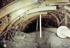
Figure 3. General condition of arched timbering without reinforcement and after longitudinal-beamed reinforcing timbering installation.
There were used 3 variants of strengthening timbering: single flanged beam with additional segment of rigidity; single flanged beam with segment of rigidity and strengthening of each arch timbering set with vertical centered chemical crutch of 2.5 m long; and two parallel flanged beams with segment of rigidity and two chemical crutches of 2.5 m long installed on each timbering frame with 30 degrees incline of their ground part in both directions from the vertical line.
The results of instrumental monitoring over an excavation roofing contour displacements and speeds of its displacement in the checked part and 3 experimental ones after implementation of strengthening timbering in 3 variants are presented at fig.4.
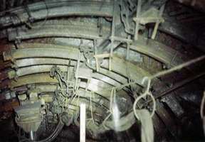
Figure 4. Diagrams of dependence of lateral rocks displacements (а) and displacement speeds (b) in ventilation drift contour in the checked part (1) and experimental parts (2-4).
As shown at submitted diagrams the longitudinal-rigid strengthening allows 2.2–2.5 times reducing of the displacements and displacement speed of the excavation roof on the most important technological part where a longwall meets a conveyer working.
4 HARD-LONGITUDE REINFORCEMENT OF ARCHED TIMBERING USED AT KALININA MINE
To define the efficient parameters of mine-workings maintenance in a zone of second workings influence in deep mines the longitudinal-rigid strengthening timbering experimental-industrial check has being conducted in KALININA Mine, in conveyer drift of the layer h10 in 2nd western longwall (fig. 5). The layer h10 “Livenskiy”, of 1.14-1.3 m wide and of 18-23° falling down angle, was worked out at a depth of 1180 m (Solovjov 2005a, b).
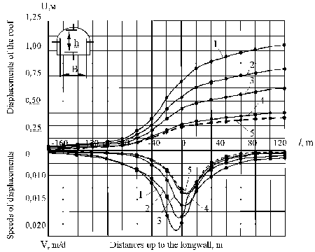
Figure 5. The mine-working plan of the 2-end western longwall layer h10 in KALININA Mine
Conveyer drift was fixed with five-linked compliant arched timbering (AP-5/13.8) made of special profile SVP-27 with a timbering frame installation step of 0.5m (fig.6-7).
There was implemented the single beamed longitudinal-rigid strengthening timbering in the drift part of 80 m length at the first stage of experimental-industrial check.
The strengthening timbering was formed of a long beam made of special rectilinear profile (SVP-27) with pieces of 4m length, connected with overlap of 0.5 m with two yokes. The beam was hung up over 2 special hooks with straps and screw-nuts in the center of every upper segment of timbering. There was installed the double-beamed strengthening timbering with a symmetric location of beams in the upper segment distanced for 1.8 m from each other to prevent intensive lateral displacements of a working contour from the side of rock bedding in the drift at the second stage.
The double beamed strengthening timbering (fig. 6) implementation allowed the perimeter of arch timbering to be used more effectively the on account of spatial consolidation of timbering sets and of a rigid frame construction creation.

Figure 6. Conveyer drift arch timbering condition without strengthening timbering implementation at distance of 120m (a) and 230m (b) from the longwall.
There was defined in the result of analysis of visual and instrumental monitoring that maximal manifestations of mountain pressure are observed along a rock roof bedding (fig. 6 a). Simultaneously during a process of a rock contour deformation there were formed local zones of the increased pressure where increased loads were focused on separate elements of timbering and rock folds were formed (fig. 6 b). Decompression of rock parts took place due to splitting and bursting of layers of roof and sides on a working contour.
To provide the working efficiency of longitudinal-rigid strengthening timbering, a beams location on the side-view of the upper segment has been changed on the third stage of the experiment. Thus one beam was located in the center of the upper segment and the other one – 0.2m upper than the arched timbering bolt – along the line of max load efficiency from a rock roof bedding (fig.7).
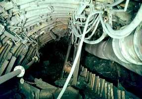
Figure 7. Conveyer drift arch timbering condition with two symmetrical (a) and asymmetrical (b) longitudinal beams implemented at distance of 120m and 230m from the longwall accordingly.
The hard-longitudinal reinforcement timbering implementation has allowed consolidating working conditions of disembodied main timbering frames on account of the increased and uneven load redistribution between overloaded and underused sets of arched timbering.
Besides the hard-longitudinal reinforcing connection presence has made preconditions for forming of local load-carrying zones to prevent the process of wrinkling forming in roofing of the layer and at sides of the excavation (fig. 6 b).
The results of instrumental monitoring of lateral rocks displacements both with reinforcing timbering installed and with none are presented at fig. 8.
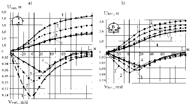
Figure 8. Diagrams of dependence of rock contour vertical (a) and horizontal (b) displacements in the layer h10, 2-d western longwall conveyer drift and of the displacements speeds (c) and (d) accordingly: 1 - on the checkpoint part with no longitudinal-beamed reinforcing timbering; 2 - on the first experi-mental area while the single central beam made of SVP-27 is implemented; 3 and 4 - on the second and third experimental areas while two symmetrical and two asymmetrical beams are accordingly implemented and the longwall is 45 m passed ahead of the transport drift face.
As it is shown at the diagrams below the single hard-longitudinal reinforcing timbering implementation allows 1.7-1.8 times reduction of roofing rocks displacements and 1.3 – 1.4 times reduction of displacements at sides of excavation.
Besides, while a longwall is 45-50 m passed ahead of a transport drift there is formed a zone of supporting pressure in preparatory mine-workings in front of breakage face, which brings to intensive displacements of rock contour.
Vertical displacements with no reinforcing timbering form 3.0 m, and horizontal – 1.5 m in alignment with longwall, and at distance of 100m behind the longwall they form accordingly 5.75 and 3.2 m. While the single longitudinal beam is implemented vertical and horizontal displacements in alignment with longwall were accordingly 0.8 and 0.4 m decreased compared with the checkpoint part, and while two beams are implemented – 1.6 and 0.75 m decreased. At distance of 100 m behind the longwall, corresponding differences of these displacements under the single beam and two beams have formed 1.5/0.65 m and 2.75/0.98 m accordingly.
Efficiency of the arched timbering set rigid junction implementation is to be explained due to changing the method of interaction between the main excavation timbering with rock parts of ingenuous roofing marginal part identified as discrete thrust surroundings.
The physical pattern of this interaction is in redistribution of underused timbering units supporting resource on account of the removal of the heavy loads from overloaded units by hard beam and their even transmission to underused timbering units. At the same time there form load-carrying vaulting consisted of ingenuous roofing rock parts over the beams along the excavation (Solovjov 2006).
Unlike usual timbering the longitudinal-hard reinforcing timbering does not allow significant displacements of separate timbering elements, it supports drawn down arches due to a rigid longitudinal rod - the beam. So under the critical loads in timbering elements there occur only minimal displacements equal to flexural deformations of longitudinal rod.
5 ANALYTICAL STUDIES OF HARD-LONGITUDINAL REINFORCEMENT TIMBERING PARAMETERS
The analytical studies with Building Mechanics method of forces implemented (Solovyov 2006b) have permitted to define the balanced length of reinforcing segment of rigidity considering the value of its central angle (fig. 9).
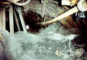
Figure 9. Scheme of loading of the arch timbering set (1) if presented the strengthening timbering (the longitudinal beam - 2 and segment of rigidity - 3)
The equations of a forces method for conditions presented on fig. 9 and 10 can be written down as following:

where δik - the beam shifts influenced by force Хk = 1 in the direction of action of force Хi = 1;
yii - the “i” arch shifts at top section from solitary force Хi = 1;
yiq - the “i” arch shifts at top segment from load qi in the direction of action of force Xi = 1.
The beam δik shifts can be found by the method of initial parameters.
Let's consider the first solitary section:
The equation of a forces method for the first solitary state is to be written down as

From here we find initial parameters:
Figure 10. Scheme of power interaction between the arch timbering sets and the beam for the first solitary state
at х = l, х = 2l, х = 3l we find shifts at points 2, 3 and 4 from action of force Х1 = 1, i.e.

The total bending moments and longitudinal forces caused by load of value qm = β q, (β> <1), pm = k qm , (m - number of an arch) and forces of interaction between timbering and longitudinal rigid beam Хm on a part of arch timbering is being defined over the following relations:

Diagrams of the bending moments and longitudinal forces in special profile of 4 arch timberings with different loading are represented at fig. 11.
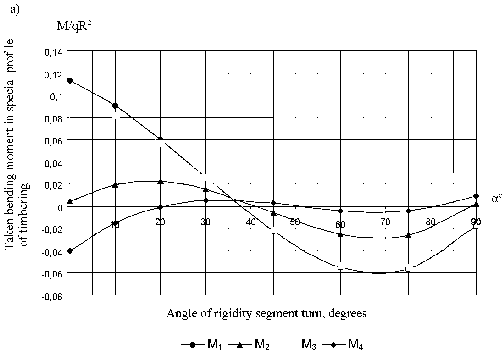
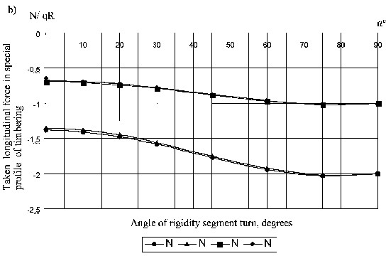
Figure 11. Graphs of the taken bending moments (a) and longitudinal forces (b) dependence from the central angle of a rigidity segment value in 4 differently loaded neighboring arch tim-bering sets
Let's define values of the bending moments and longitudinal forces on border of a rigidity segment of the first arch (m = 1) over one special profile №22, φ = 35°, Wmax = 81,33 sm3,Wmin = 74,8 sm3, F = 27,91 sm2.
М = 0,06049·153,6 = 9,292 кНм, N = - 0,81026·76,8 = - 62,23 кН.
Tensions in external fibres:

Mine
Tensions in internal fibres:
Mine
Thus, both compressing and stretching tensions in a rigidity segment are less than allowable ones for the Item 5 ([σ] = ± 240 MPa).
The tensions arising in arch timbering made of special profile №22 are less than allowable ones.
6 CONCLUSIONS
Thus, as a result of efficiency analysis of the different methods of stability providing in taking-out excavations of deep mines in the area of the second works influence, the com-bined method of excavation protection is to be admitted as efficient. To provide it the rigid cast band made of cement-mineral solution is raised behind the longwall along the excavation, and 3 steel-polymeric crutches in roofing of the layer combined with two longitudinal beams made of SVP-27 are radially installed in developments pit-face (fig. 12).
Successful experience of use of the combined protection methods and maintenance facilities of the intensively deformed preparatory excavations in "Yuzhnodonbasskaya №3" and "Krasnoarmeyskaya-Western №1" mines allows to make a conclusion about possibility of their implementation in deep mine of Donetsk region.
The longitudinal-beamed reinforcing timbering combined with cast band and the layer roofing crutching is to provide the reduction of the expenses on the system of chemical crutches installation and allows arched timbering units consolidation along the taking-out area to maintain the preparatory mine-workings stability on different areas of the second works influence.
BIBLIOGRAPHIE:
- Якоби, О. 1987. Практика управления горным давлением. Пер. с нем. 566 с. Москва: Недра.
- Литвтнский, Г.Г. & Гайко, Г.И. & Кулдыркаев, М.И. 1999. Стальные рамные крепи горных выработок. 216 с. Киев: Техніка.
- Байсаров, Л.В. & Демченко, А.И. & Ильяшов, М.А. 2001. Охрана штреков литыми полосами при разработке пологих пластов средней мощности. Киев: Уголь Украины. #9. C.3-6.
- Байсаров, Л.В. 2003. Ресурсосберегающая технология крепления и производства работ по возведению литых полос при поддержании конвейерных штреков. Геотехническая механика: Сб. науч. тр. ИГТМ НАНУ. №47. Днепропетровск: С.46-52.
- Ильяшов, М.А. & Байсаров, Л.В. 2006. Новые технологические решения в охране концевых участ-ков высоконагруженных лав. Геотехническая механика: Сб. науч. тр. ИГТМ НАНУ. Днепро-петровск: #61. С.79-92.
- Петренко, Ю.А. & Касьян, Н.Н. & Новиков, А.О. & Сахно, И.Г. 2004. Новый подход к расчету параметров анкерной крепи. Физико-технические проблемы горного производства. #7. Донецк: С.162-172.
- Касьян, Н.Н. & Петренко, Ю.А. & Новиков, А.О. & Гладкий, С.Ю. & Сахно, И.Г. , 2006. Исследование влияния схем анкерования массива на устойчивость выработок. ХII Международный симпозиум «Геотехника-2006». Гливице-Устронь: С.455-467.
- Бондаренко, Ю.В. & Соловьев, Г.И. & Захаров, В.С. 1999. Изменения деформаций контура кровли выемочной выработки при использовании каркасной крепи усиления. Известия Донецкого горного института. #1. Донецк: С.66-70.
- Соловьев, Г.И. & Панфилов, Ю.Н. 2005a. О продольно-жестком усилении основной крепи подгото-вительных выработок глубоких шахт. Известия Тульского государственного университета. Тула: С.177-185.
- Соловьев, Г.И. 2005b. Определение параметров продольно-жесткой усиливающей крепи для вые-мочных выработок глубоких шахт. Горный информационно-аналитический бюллетень, МГГУ. Москва: #9,. С. 230-233.
- Соловьев, Г.И. 2006. Особенности физической модели самоорганизации боковых пород на контуре выемочной выработки при продольно-жестком усилении арочной крепи. Науковий вісник НГУ. Дніпропетровськ: #1. С.11-18.