
King Fahad University of Petroleum & Minerals
Computer Engineering Department
COE-543 Mobile and Wireless Networks
Final Report
QoS Design for 3G Networks
Name: Abdullah Hamad Al-Subhi
ID # 913659
Date: May 20, 2003
Table of Content
1. Introduction ………………………….…………………………. 2
2. QoS in 3G Networks …………………………….……...…….. 5
2.1 UMTS ……………………………………………………. 5
2.2 CDMA2000………………………………………………. 8
3. 3G QoS Techniques ……………………………….…………. 10
3.1 Traffic shaping and policing ………………………...... 10
3.2 Traffic Scheduling Algorithm …………………………. 14
3.3 DIFFSERV based QoS Architecture ……………... 16
4. QoS Issues in the Converged 3G and Wired Networks 18
5. Conclusion …………………………….………………………. 21
References
Introduction
The goal of third generation (3G) mobile communication systems is the delivery of multimedia services to the user in the mobile domain. This requires the provision of user data rates that are substantially higher than those provided by today’s second generation (2G) networks. In 2G, only data rates of 9.6 kbit/s are currently supported. In 3G users will be provided with data rates of up to 144 kbit/s in macrocellular environments, up to 384 kbit/s in microcellular environments and up to 2 Mbit/s in indoor or picocellular environments. These requirements address the limitations of 2G, which, despite its enormous world-wide success was designed primarily for mobile digital telephony with only a limited data capability.
3G Network enables provides high-speed wireless Internet access to mobile users. The same network can be used to make voice calls using conventional mobile phones. Moreover 3G networks are seen as the enabler of multimedia services like videoconferencing, streaming audio and video etc. These Networks must provide services to many different types of applications without letting data from one application affect the services provided to other types of applications. In other words, 3G Networks must provide Support for Quality of Service.
In 3G wireless Internet, controlling QoS is not about throwing bandwidth at the ‘hot spots’; as a matter of fact, the hottest spot in the network is the radio access portion, the most expensive part of the network. It is about making the best use of available network resources to deliver QoS as required and subscribed by the services and users. Applying policies to QoS control will help to differentiate users and services, as well as to protect higher-tier users and network resources.
The ability to control QoS offers operators ways to differentiate themselves from other competitors by being able to launch new revenue-generating services faster and to bundle service packages for different user segments. Absence of this ability remains prevalent with most fixed and wireless ISPs today, making them resort to “first come first served ”or “all you can use”’ service models.
What is Quality of Service?
Quality of Service carries different connotations for different people. It is the end users who pay for the service, and whose perspectives matter most. From an end user’s perspective, QoS defines the characteristics of service delivery that impact most critically his/her perception of the service. The three main characteristics of a network delivering QoS to an end user are as follows:
Availability of the service: the service is immediately available or reasonably delayed depending on user’s subscription status. The service availability is faster for a higher-tier subscriber than that for a lower-tier subscriber.
Quality of information: the information is received uncorrupted and usable without errors, as required by the type of the service.
Consistent delivery: The information is delivered throughout the session at a perceivably consistent speed and quality, guaranteeing that the perception of the user remains the same throughout.
At a technical level, QoS is characterized by a set of measurable parameters such as:
• Service availability
• Delay
• Delay variation (jitter)
• Throughput
• Packet loss rate
Service availability can be further broken down into percentage of blocked and dropped calls, as well as the duration of service outages. QoS enables a network to deliver classes of service (CoS), i.e. different prioritized treatments to different services or to different groups of users. QoS allocates network capacity by type of traffic required by certain type of service, while CoS provides preferred allocation of the network without guaranteeing any measurable amount. CoS is implied in a QoS policy associated with a subscriber. It is used by the network to provide differential QoS treatments to different services subscribed by different users, that is, service and user differentiation.
2. QoS in 3G Networks
2.1 UMTS
2.1.2 UMTS QoS Architecture
In order to have QoS functionality, it should be configured from the source up to the destination. The traffic moves from Terminal Equipment (TE) to another TE through all network services. The UMTS bearer services consist of two parts: Radio Access Bearer (RAB) and Core Network Bearer (CNB) services. These two services used to optimize the UMTS bearer service in a network topology taking into consideration mobility and mobility subscriber profiles [S1:1187].
The RAB service provides a secured transport of signaling and user data between MT and CN edge with QoS adequate to negotiated UMTS bearer service and with the default QoS for signaling. The RAB is based on the radio interface behavior and maintained for moving MT [S1:1188].
UTRAN and MT have the ability to segment/resemble the user flow into different sub-flow requested by the RAB service. The segmentation/resemble is provided by the Service Data Unit play load format singled at the RAB establishment. The radio bearer service handle the part of the user flow belonging to one sub-flow based on sub-flow reliability requirements. [S1:1188].
The CNB role is to efficiently control and use backbone network to provide the contracted UMTS bearer service. The UMTS packet CN support different backbone bearer services for different QoS [S1:1188].
The CN nearer service uses a generic network service. The backbone network service covers the layer 1 and layer 2 functionality and is selected according to operator’s choice to satisfy the QoS requirements of the CN bearer service [S1:1188].

Figure 1. UMTS QoS Architecture
2.1.3 UMTS QoS Classes.
UMTS network should take care of different obstacles in providing good services in the air and consider all limitations on that aspect. Some real time application can’t afford much delay of packet data being transmitted to have good quality services provided by such an operator. UMTS QoS defines some classes which take care of limitations of the air interface. UMTS define four different classes:
Conversational class.
Streaming class.
Interactive class.
Background.
The conversational and streaming classes are used to carry real-time data or services. Delay is what distinguishes between them in how are they sensitive to it. Conversational class is treated to be the most critical service amonth them because it carry the voice and vido telephony [S1:1189].
The interactive and background classes are mainly used for traditional services like email and FTP. These kinds of services do not need to be delivered on time. They are less sensitive to delay where it accepts reasonably long delay like telnet and some very long delay like email [S1:1189].
|
Traffic class |
Conversational class
|
Streaming
class |
Interactive
class |
Background
class |
|
Fundamental characteristics |
- Preserve time relation (variation) between information entities of the stream - Conversational pattern (stringent and low delay ) |
- Preserve time relation (variation) between information entities of the stream |
- Request response pattern
|
-Destination is not expecting the data within a certain time -Preserve payload content |
|
Example of the application |
voice |
streaming video |
web browsing |
telemetry, emails |
Table 1 UMTS QoS Classes
2.1.3 QoS Management
The control plane QoS management functions include: [S1:1189].
Service manager coordinates the function of the control plane for establishing modifying and maintaining the service.
Translation function performs conversion between UMTS bearer services attributes and QoS parameters of external network service control protocol.
Admission/capability control maintains information about all available resources of the network entity and about all resources allocated to UMTA bearer services.
Subscription Control checks the administrative rights of the UMTS bearer service user to use requested service with specified QoS attributes.
User Plane QoS management function maintains the signaling and user data traffic within certain limits defined by the QoS attributes. It includes: [S1:1189].
Mapping function provides each data unit with the specific marking required to receive the intended QoS at the transfer by a bearer service.
Classification function assigns data unites to the established service at the MT according to the related QoS attributes if the MT has multiple UMTS bearer services established.
Resource manager distribute the available resources among all services sharing the same resource based on the required QoS.
Traffic conditioner provides performance between the negotiated QoS for services and data unit traffic. It handles that by using policing and traffic shaping techniques. The policing function compares the data unit traffic with the related QoS attributes. The traffic shaping form the data unit traffic according to the QoS the service.
2.2 CDMA2000
2.2.1 QoS implementation
The architecture for provisioning QoS should take into account the need for application and subscriber differentiation. The wireless network should be able to handle various types of applications with vary QoS objectives while optimizing the utilization of system resources. Applications are classified into two types, the real-time and non-real-time application [S2:45].
CDMA2000 define two modes of QoS:
Non-assured Mode QoS: The application with non-assured QoS mode is characterized by the delivery of packets by mean of best effort scheduler. There are no strict requirements on packet transfer delay and data rate. “Priority” parameter is specified for QoS [S2:48].
Assured Mode QoS: Applications with assured QoS mode can assign some parameters define the required packet transfer delay and acceptable data rate. The QoS profile of this mode is characterized by the following parameters: [S2:48].
Priority.
Data Rate: Mobile station can specify the data rate (8, 32, 64,144 and 384kbps).
Data Lose Rate: Mobile station can specify the requested data loss rate or acceptable data loss rate (1, 2, 5 and 10%).
Maximum Delay: Mobile station can specify how long data octets can be kept in the transmit buffer (40, 120 and 360%).
QoS architecture
The end-to end QoS architecture is designed such that the objective specifying by the QoS profile of an application is implemented by utilizing the following services:
Radio Bearer Service: The telecommunication segment between MS and RAN. It supports multiple applications simultaneously. The QoS parameters is defined such that to deliver user application requirements. In this segment, the QoS relies on the efficient implementation on some control techniques [S2:49].
Power Control: The fast feedback power control with a channel feedback at the rate 800Hz ensures a minimum transmission of power, low level of user interference in the cell and very efficient utilization of radio resources.
Radio Admission Control: It checks if QoS requirements of the new service instance can be met before it is accepted.
Radio Resource Control (RRC): It establishes, maintains and terminates radio resources for exchange of packets between the MS and RCF. It maintains knowledge of radio resource status and broadcast packet zone ID in the system overhead message.
Scheduling: It schedules data packet in the forward link. Round robin scheduling is the widely used algorithm.
R-P bearer Service: The telecommunication segment between RAN and PDSN (Core Network). The PDSN first conducts authentication and authorization for MS with the Home AAA. The PDSN retrieves the QoS profile from HAAA through local AAA. The subscriber’s QoS profile is mainly characterized by the following information: [S2:49].
The differentiated service markings
The Air-Link QoS attributes.
Call Admission Control: It is to admit and deny R-P connection. It is based on the following criteria:
Availability of sufficient RN resources for new connection.
QoS requested by the user is within the limits sets by the user’s QoS profile.
QoS Transport in R-P interface: The QoS requirements are specified for each service instant independently. A single PPP session is established between MS and PDSN for each R-P session where each PPP/R-P session supports communication flows for multiple IP addresses belong to the same MS [S2:49].
External Bearer Service: The telecommunication segment between PDSN and the external private network. There is no CDMA2000 specific QoS implementation for external network where it relies on the standard IP mechanisms [S2:50].

Figure 2 CDMA2000 QoS Architecture
2. QoS Techniques used in 3G Network
2.1 Traffic shaping and policing
2.1.1 Definition
Traffic conditioning provides conformance of input traffic to the specifications agreed with the bearer service provider. A traffic conditioner may achieve this by traffic shaping or/and traffic policing. The traffic conditioner may be embodied both in a User Equipment (UE) and in the gateway nodes [S3:139].
Two main traffic shaping algorithms are exist , namely Leaky Bucket Algorithm defined by ATM Forum and Token Bucket (TB) Algorithm defined by IETF respectively. TB has been adopted as a reference algorithm for traffic conditioner in UMTS by 3GPP [S3:139].
2.1.2 System Model
A traffic conditioning-enabled Radio Network Subsystem (RNS), which is composed of a RNC and one or more Node Bs is depicted in Fig. 1 as the system model. The UEs are distributed within each cell with an omnidirectional base station at the cell center. Each UE is expected to use any one of the considered traffic classes. A traffic shaper is employed for uplink traffic on each UE. The packets received at the Node Bs are forwarded to the RNC where the traffic policing function is performed [S3:139].
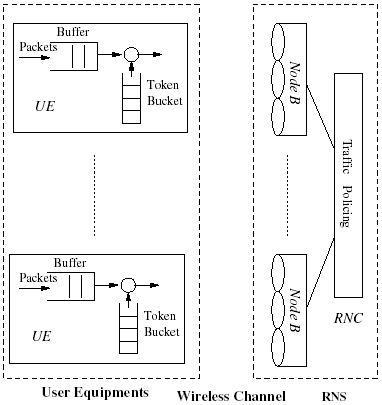
Figure 3. System Model: Traffic Shaping and Policing in UMTS
Token Bucket Algorithm:
The token bucket algorithm regulates the bursty traffic in such a way that over a long time period the average allowed rate approaches the desired token rate r asymptotically and over a short time interval the burst size of the traffic is upper bounded by bucket size b. The TB algorithm implementation is illustrated in Fig. 4, where Token Bucket Counter (TBC) is an internal variable used to record the number of the remaining tokens at any time. With this implementation, three corresponding measures may be taken when a new packet arrives [S3:140].

Figure 4. Token Bucket Algorithm
Case 1: conformed at arrival. The size of the incoming packet is smaller than the TBC value in the bucket when the packet arrives. The packet is compliant at arrival and is marked as a compliant packet [S3:140].
Case 2: non-conformed. A packet is deemed as noncompliant if its length is larger than the bucket size. This type of packet is tagged as not-compliant and will not be dropped at the UE, but left for preferential discarding at the traffic policing point in case of channel congestion [S3:140].
Case 3: shaped to be conformed. The size of packet is not larger than the bucket size, but larger than the TBC value at arriving instant. In this case, the packet will be enforced to wait by the traffic shaper until there are enough tokens in the bucket. This type of packet is shaped to be conformed and marked as compliant after shaping [S3:140].
2.1.3 Traffic conditioning scheme in UMTS
Traffic conditioner provides conformance between the negotiated
QoS and the data unit traffic [S3:140].
Traffic Shaping at the UE
The traffic shaping scenario at the UE is shown in Fig. 5. The TB shaper verifies the conformance of a packet according to corresponding token bucket parameters, shaping the traffic when necessary. As a result, the regulated traffic after shaping will be categorized into two types, either compliant or noncompliant. They are left for further policing at the RNC [S3:140].
The scenario will introduce traffic shaping delay which consumes part of the total end-to-end delay budget of a service, but the regulated flow is expected to have a lower packet loss ratio instead.
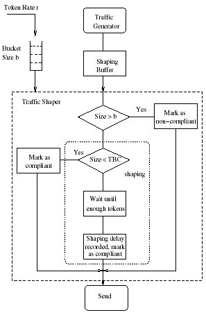
Figure 5. Traffic Shaping at the UE
Traffic Policing at the RNC
The traffic policing function compares the conformance of the user data traffic with the QoS attributes. Within the capacity of the Bearer Service (BS) manager, policy control is a logical policy decision element which is optional to the UEs and required to the gateways. Traffic policing policy in practice is a network operator choice. As depicted in Fig. 6, the policing function consists of traffic classification and policing functionality and is embodied at the RNC[S3:140].
The classification function checks the header of every received packet and forwards the corresponding information for further policing, according to its traffic class as well as conformance status [S3:140].
The policing element at the RNC will perform corresponding policies on each individual packet. For non-compliant data packets, they will be acknowledged only if the channel is not congested, i.e., the total interference level by summing of all connections does not exceed the threshold. Otherwise they will simply be discarded. For non-compliant data packets, the load calculation will take into account both compliant and non-compliant packets at first, if the load exceeds the threshold, the non-compliant packets will be dropped preferentially. A conformed packet could also be discarded if there are too many concurrent compliant packets on the channel [S3:141].

Figure 6. Traffic Policing at the RNC
2.2 Traffic Scheduling Algorithm.
2.2.1 Definition
In packet radio communication several issues of random nature make this task especially difficult to achieve: packet generation from many sources hat must be multiplexed within a limit set of share resources plus variable propagation characteristics. The policy followed by the scheduling algorithm should lead to a system behavior as close as possible to the desired one. The soft-QoS requirement for delay sensitive services can be established in terms of certain desired delay and threshold boundaries [S4:1082].
2.2.2 Scheduling Strategy
The Radio Resource Management (RRM) strategy can be split into there different steps:
Prioritization
All user want to send data must be classified based on type of service (1st priority level). If it is the same service then it is classified based on QoS profile. QoS is defined here by the mean of amount of data to be send and the time remaining to keep the delay below the desire one. The smaller the deadline the higher position in the queue will be. RRM based on this queue decide on which traffic to send first [S4:1083].
This expression assign higher priority to
those users with either much data to send or much time already
waiting for permission.
Li Packet length remaining to be sent.
TOi Time left until packet deadline for the consider service.
Capacity requirement
This step is performed by user from heist to lowest priority. In order to satisfy the current user QoS requirement some system capacity should be considered to this user as well as certain transmission rate should be reserved for this user. It should be handled smartly by the scheduler so that the overall system behaviors were as optimum as possible [S4:1083].
For WWW-link services, there are many to be factors to consider before a design about of capacity to be assigned to the user can be taken. For example, making consistent the priority level to the radio link quality required for data transmission, then a higher priority indicates urgency to transmit that data. In this case a low Frame Error Rate (FER) should be guaranteed to avoid as much as possible retransmission which lead to more delay. The higher the higher the priority level the lower the FER at the receiver side should be. FER requirement should be limited otherwise one user could demand the whole capacity of the system [S4:1083].
Availability check
Once the capacity requirement for the current user has been decided, the scheduler must check that a feasible solution do exists to satisfy at the same time both the current user requirement and those other users with higher priority that have already been accepted for transmission [S4:1084].
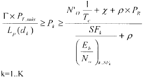
The scheduler should take the interference model into account in order to devise the expected (E/N) for all users. For the uplink , the scheduler evaluates the following equalities:
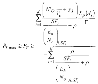
For the downlink, the scheduler evaluates the following equalities:
|
Pk Kth user. SFk Kth user spread factor. No Thermal noise spectral density. X Inter-cell interference. P Orthogonal factor |
Tc Chip duration (Eb/No)k,SFk Kth user requirment PT-max Max transimted power PR total recive power dk distance from Kth user to BS
|
DIFFSERV based QoS Architecture.
Having as less as possible Delay-jitter is the main concern of streaming services in #G network. Two approaches to achieve of this goal. First, Streaming Proxy Agent should be used at the edge of 3G core Network to smoothen the incoming traffic. This will make it independent of service model used in the Internet. Second, a Probing based approach is used to select minimum delay-jitter delivery path through the DiffServ cloud. Key components of the proposed Architecture: [S5:1898].
Multicast Model [S5:1900].
IPIM-SM multicast routing scheme is proposed to model mobility in the architecture. The mobile host assigned a temporary multicast address within the domain. Since at a given time there is only one receiver and one sender for a given session in mobile environment. PIM-SM needs additional message to disable forwarding of packets in passive branches. Messages in the PIM-SM protocol:
PIM Active Join.
PIM Passive Join.
It can be easily implemented by associating an active/passive flag with multicasting forwarding entry at intermediate routers
Mobile Proxy Agent [S5:1900].
It acts as a proxy for the mobile host to make sure that data is delivered to the mobile host through the best possible path. It performs the following functions:
Initialize the connection for mobile host in its cell by sending PIM active join to RP and prompts the mobile proxy agents in the neighboring cells to send PIM Passive Join message forwards RP.
Implements a measurement based scheme that that uses the information carried in probing packet header to determine the delay characteristic for different services class.
Sends the periodic feedback to the source node regarding the service class giving thee best delay-jitter performance.
Streaming Proxy server agent [S5:1900].
It resides at an entry-level border router of the 3G Network. It performs the following functions:
To smooth the incoming streaming traffic to remove delay-jitter accumulated as streaming traffic traverses the rest of the internet.
To perform the additional functionality of trans-coding. It is need for example if a user from high bandwidth network to low bandwidth network.
To send probing packet mapped to different services class to the Mobile Proxy Agent. Probing packets carry the time-stamp, which helps the Mobile Proxy Agents to calculate the delay-jitter for different services classes and send feedback to the SPS.
Seamless QoS using probing-based approach [S5:1901].
When the mobile moves to a new cell, a new data path is established between SPS and the client. The new path may have different delay characteristic for a giver service class. When a streaming session is initialized in a cell, the Mobile Proxy Agent of the current cell issues PIM Active Join to the multicast tree and the mobile proxy agent in the immediate neighbor cell issues PIM Passive Join message toward the multicast tree.
4. QoS Issues in the Converged 3G and Wired Networks
Introduction
The wired networks have been developed long time ago and so many design efforts has been spent to become with reliable and scalable designs such that meet most of the required services which concern on QoS. The wireless domain doesn’t have that much effort spend on and it is very hot area. The QoS procedures are slightly different from wired network because the air interface in case of wireless network play a major role of signal degradation caused by different aspect like delay and jitter where these can of aspects are not there in the case of wired network[S6:44].
The RCL Architecture
The resource control layer (RCL), Figure 7, which is based on the bandwidth broker (BB) concept. RCL is designed as a hierarchical and distributed BB to overcome potential scalability problems. The three key components of RCL are the resource control agent (RCA), the admission control agent (ACA), and the end-user application toolkit (EAT) [S6:46].
The RCA represents the ultimate principle in an administrative domain concerning the management of network resources Moreover, it has the overall view of the policies enforced in a domain, and decides on the router configuration and management of the bilateral service level agreements (SLAs) between adjacent administrative domains[S6:46].
The ACA mainly performs user authentication and authorization, reservation handling, and admission control. Policing and admission control are made only at the edges of the network; therefore, the corresponding ingress and egress points (ingress-egress ACAs) of the flow are identified, and the resources are checked to ensure that the new flow can be accommodated [S6:46].
Reservation requests are forwarded to the ACAs from the EAT, which mediates between end users or applications and the network. The EAT interacts with the ACA to be aware of the available network services[S6:46].
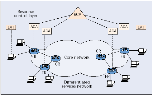
Figure 7. The RCL architecture and main components.
Network Services and Traffic classes
In the RCL architecture five traffic classes have been defined: premium constant bit rate (PCBR), premium variable bit rate (PVBR), premium multimedia (PMM), premium mission critical (PMC) and best effort (BE). Applications with similar requirements on the network in order to perform effectively can be grouped into this relatively small number of classes. The scheduling mechanism actually implemented is a combination of Priority Queuing (PQ) and Weighted-Fair Queuing (WFQ), called PQWFQ. A queue is dedicated to PCBR, which has strict priority over the others, while the other traffic classes are scheduled with WFQ. A WFQ weight is assigned to each traffic class, and each queue is managed by different queuing strategy: Drop-Tail, Random Early Detection (RED), or Weighted RED (WRED). A specific traffic profile is determined for each traffic class that best characterizes the data source [S6:46].
Mapping QoS Traffic Classes
Table 1 contains the proposed mapping. Its justification is confirmed by examining the characteristics and traffic attributes for these classes.
The conversational and streaming classes are associated one-to-one to PCBR and PVBR, respectively. The main discrepancy stemming from the table deals with the maximum bit rate and packet size, due to the strict limits defined in RCL [S6:47].
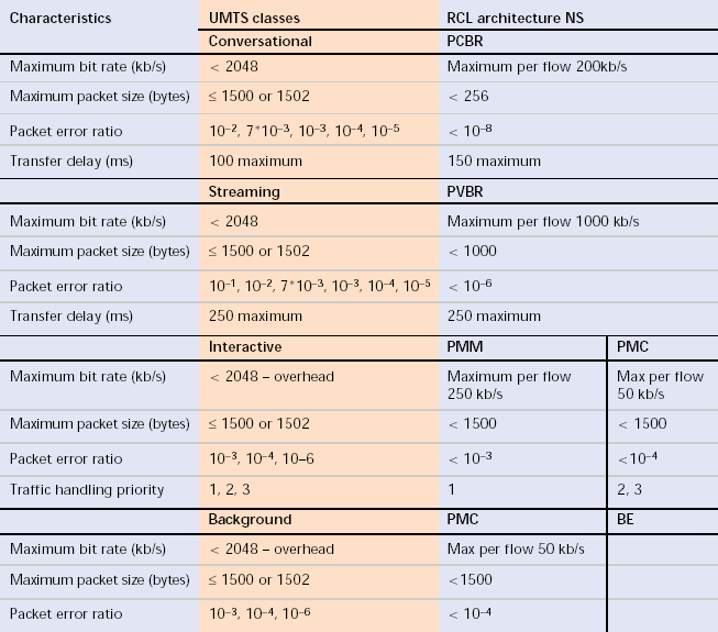
Table 2. Mapping of UMTS QoS classes to RCL network services.
Table 3 proposes a possible transformation, although for some attributes such transformation may not be necessary or possible. Attributes like transfer delay and packet loss are redundant, because they are used only for the selection of the appropriate traffic class. Moreover, there are attributes of the UMTS BS that deal only with UMTS aspects, such as the source statistics descriptor, which is used for calculating a statistical multiplex gain for use in admission control. Such attributes are not used in the transformation process [S6:48].
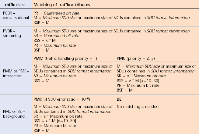
Table 3. Transformation of QoS service attributes.
Control and User Plane Internetworking
in order to establish and maintain the end-to-end service, the QoS management functions of both networks at the control plane must be able to interoperate. Typically, there are two general ways to accomplish that, directly or indirectly [S6:49].
The direct way implies that their mechanisms are aware of the details of each other, and the signaling protocol can be a proprietary one. This scenario ensures that the mapping among the traffic classes can be tuned to the best possible way [S6:49].
The indirect way neither makes use of a proprietary signaling protocol nor requires the QoS management mechanisms to be aware of each other. This scenario is most appropriate in the case of independent service providers that do not have specific inter-domain partners [S6:49].
5. Conclusion
UMTS classified traffics according to their sensitivity from delay and jitter-delay in case of real time services. Four such classes are defined to distinguish between different types of traffic in order to treat them according to their importance. QoS management also proposed to manage shared resources among all users according to each user QoS profile preferences. QoS define certain attributes to each class.
Two QoS modes are defined in CDMA2000 to handle classification of traffic in the network for QoS purposes. A non-assured mode, which characterized by packet delivery by mean of best effort scheduler. The second mode is assured mode, which specify acceptable transfer packet delay and data rate. Each part of the CDMA2000 network components has its role in QoS to ensure QoS task effectively. It is handled in Radio Access Network, the Core Network and External Network as well.
Some issues try to target some enhancement techniques to handle QoS in 3G warless network. Some existence techniques are modified to meet the complexity of on the air services which doesn’t to be there for wire network services. One of such technique is traffic shaping and policing which address traffic conditioning by applying different proposed algorithms. In 3G network (UMTS) the traffic shaping done at the User Equipment and the traffic policing done at the Radio Network Control.
Another technique address QoS in 3G Networks is scheduling algorithm for soft-QoS. It is split into three main steps to guarantee soft-QoS. It prioritizes the service traffics. Then it tries to carry out user by user from highest to lowest priority according to the capacity requirements. Lastly, it checks for resources availability for the user being processed.
Another technique also tries to differentiate between services and treat critical application like streaming application accordingly. The main purpose here to minimize jitter-delay delivery path to get better streaming service in the network. The idea of streaming proxy server is proposed to handle jitter-delay and provide smooth incoming streaming traffic.
References
Integrated QoS support in 3G UMTS networks, Garg, V.K.; Yu, O.T.W.;Wireless Communications and Networking Conference, 2000. WCNC. 2000 IEEE , Volume: 3 , 2000 Page(s): 1187 -1192 vol.3
QoS implementation in CDMA2000,Rao Yallapragada; Personal Wireless Communications, 2002 IEEE International Conference on , 2002 Page(s): 45 -50
QoS provisioning using traffic shaping and policing in 3rd-generation wireless networks,Frank Yong Li; Stol, N.; Wireless Communications and Networking Conference, 2002. WCNC2002. 2002 IEEE , Volume: 1 , 17-21 Mar 2002 Page(s): 139 -143 vol.1
A scheduling algorithm for soft-QoS guarantee in 3G systems Sallent, O.; Perez-Romero, J.; Agusti, R.; Casadevall, F.; Vehicular Technology Conference, 2001. VTC 2001 Spring. IEEE VTS 53rd , Volume: 2 , 2001 Page(s): 1082 -1086 vol.2
Diffserv based QoS architecture to support streaming applications in 3G mobile networks Venna, S.; Barnes, R.; Personal, Indoor and Mobile Radio Communications, 2002. The 13th IEEE International Symposium on , Volume: 4 , 2002 Page(s): 1898 -1903
QoS issues in the converged 3G wireless and wired networks Maniatis, S.I.; Nikolouzou, E.G.; Venieris, I.S.; IEEE Communications Magazine , Volume: 40 Issue: 8 , Aug 2002 Page(s): 44 -53