Adaptive real-time object recognition for augmented reality
Автор: Ondrej Popelka, David Prochazka, Jan Kolomaznik, Jaromir Landa, Tomas Koubek
Источник: www.researchgate.net ...
Автор: Ondrej Popelka, David Prochazka, Jan Kolomaznik, Jaromir Landa, Tomas Koubek
Источник: www.researchgate.net ...
Abstract: One of the key features of virtually all object recognition systems is the ability do deal with occlusions of detected objects. This article is focused on identification of occluded artificial objects such as square markers. The article reviews frequently used methods for detection of partially occluded markers. Further, our implementation of two object recognition methods is presented. The first method is based on morphological operations. The other one is based on a SURF feature extraction and matching. Finally, our adaptive detection method that takes the best from both implementations is described. Presented method is especially useful for real-time applications such as augmented reality systems.
Keywords: Augmented Reality, Marker, Occlusion, SURF, Golay error correction code, Image processing
Computer vision is an area with many uses in the mainstream applications, even in the consumer electronics. Among others, it is possible to mention autonomous security systems with ability to detect particular objects, game console controllers that are able to identify player movements (e.g. Microsoft Kinect or Playstation Move) or visual search engine such as Google Goggles.
A special subset of these applications is based on marker recognition. Generally speaking, marker is an artificial pattern that can be easily identified in the camera image. Markers can be in form of black-and-white dots (frequently used by optical scanners), circles or even squares [3]. The last mentioned form is frequently used by many augmented reality applications from computer games (e.g. ARhrrrr! described in [6]) to professional applications [9].
We are able to observe a huge emergence of natural object tracking: already mentioned optical tracking of player movements by Microsoft Kinect, diffeerent ubiquitous interfaces based on gestures, professional marker-less optical 3D scanners etc. From this point-of-view, the area of artificial object tracking can easily look obsolete. Nevertheless, we dare to argue that this is not the case.
Many optical scanners still use the markers for more precise alignment even though they are able to recon- struct the shape without them (e.g. GOM Atos). Also the movie motion capture is still frequently based on usage of diode markers. The same situation can be observed in the area of human-computer interaction. It is possible to control the application using simple gestures (pinch and zoom, pan etc.), however, in many cases the usage of markers allows more precise input or even new features that are virtually impossible to implement without markers.
As an example, an augmented prototyping application described in [14] can be taken. Markers placed on car prototype surface represent diffeerent car parts that are inserted into the scene. Complexity of a appropriate 3D model selection and complexity of position adjustment within a scene are rising substantially with the amount of required parts. Even the sole intricacy of precise position adjustment of a single 3D model is not negligible. On the contrary, adding a square marker into a scene is natural and straightforward. Theoretically, the marker could be replaced by a natural object in this case. However, the usage of natural object could significantly decrease the precision of pose estimation and even more it introduces the problem of diffeerentiating between several similar natural objects. Therefore, such replacement would be counter-productive in this kind of application.
[11] describes a few recognition and classification methods that can be used for feature description in marker detection process. These methods include e. g. learning systems, multidimensional classification or neural nets, but they are rather applicable for decision making process. Existing real-time augmented reality applications use other approaches. Generally, there are two approaches usually used for a marker recognition. Both are described in [16]. The following section outlines their key principles and presents selected representative projects.
This group of detection methods represents approaches such as SIFT (Scale-invariant feature transform) [8] or SURF (Speeded Up Robust Features) [1]. These methods are based on keypoints detection. The keypoints are various regions of interest: edges, corners, blobs. When detected, the keypoints have to be matched against template (either natural or artificial) keypoints. This matching process requires that both keypoints to be matched are described by gradient changes in their neighbourhood. The process of keypoint neighbourhood description is usually called feature extraction. The output of this process is a set of feature descriptors. Camera image descriptors are then compared to template image descriptors so that camera image and template may be matched.
For our implementation we have chosen the SURF algorithm because it has a good ratio between detection capabilities and performance. Marker detection using the SURF algorithm is composed of three steps: detection of keypoints (points of interest), feature extraction and keypoint matching. Detection of image keypoints that are used for the image description is based on gradient changes in the grayscale version of the image. Each keypoint is identified by position and a circular keypoint neighbourhood in which the gradient changes are evaluated. Then the process of feature extraction is performed. During this process, each keypoint neighbourhood is described using 64-dimensional or 128-dimensional vector that describes the gradient changes of each keypoint neighbourhood.
To determine whether a marker is present in an image, the descriptors computed from a template and descriptors computed from the camera image need to be compared. The keypoint similarity is determined by gradient changes in the keypoint neighbourhoods that are represented by feature descriptors. If the image contains areas with similar gradient changes, these areas will be identified as same or similar keypoints. In general, this is the most problematic part of the feature based marker identification. Comparison of descriptors, advantages and disadvantages of diffeerent feature based approaches is described in [17].
Methods in this group are based on partial image morphology reconstruction. Well-known ARToolKit uses recognition based on line detection. An ARToolKit marker is designed as black-and-white picture inside a black rectangle. As described in [5], image pre-processing is followed by connected pixels clustering. Subsequently, contour of each connected pixels cluster is found and points that represent marker corners are used for homog- raphy computation. This homography matrix is used for perspective correction of found marker. Furthermore, template matching is used for marker identification. A picture inside the black rectangle must be compared with stored patterns (templates). The marker is identified on the basis of correlation with a template.
ARTag is based on another approach described in [4]. In this project similar markers as in the ARToolKit are used. The main diffeerence is that a black-and-white pattern that represents a binary code is inside the border. Detection of borders that is based on edge pixels identification and their clustering into lines is used for marker recognition. Consequently, quadrangles are created from intersected lines. Quadrangle corners are then used for homography computation. Finally, the error correction code inside the marker border is used for marker identification. This edge pixel clustering method allows the ARTag to deal with partial marker side occlusions. However, it cannot deal with a corner occlusion.
In a system called RUNE-tag [2] dots arranged in a disc are used. The disc is partitioned into sectors and each sector can be divided into concentric rings. In each concentric ring a dot can be placed. According to the authors, by placing dots at diffeerent circles, it is possible to create up to 20,000 diffeerent markers and recognize the marker with occlusion up to 2 3 of the dots.
[13] proposed a hybrid method that combines a edge based marker detection method with a feature detection. Among the marker corners, features within the marker are detected. Once the marker corners tracking fails, feature tracking on previously detected features is performed. This approach is used for overcoming both the occlusion and jitter problem.
Two marker detection approaches were implemented in our application { morphology based detection and S-G detection. The former one is fast, nevertheless, it is not able to deal with occlusions. The latter is based on feature extraction and matching. Although it is able to deal even with substantially occluded markers, its performance is significantly lower. All outlined operations were implemented using tools provided by the OpenCV library [7].
Presented approach is composed of following well-known steps: camera image pre-processing, morphological analysis of pre-processed image and searching for a marker within morphological image description. Its general idea is based on approach presented in [5]. The pre-processing step consists of grayscale conversion, removal of unnecessary details using gaussian blur and finally adaptive thresholding. The gist of this phase is to remove from the image as many details as possible, because the amount of details has a direct in uence on the performance.
In the second step, contours are detected within the thresholded image and through the morphological analysis a list of detected polygons is constructed. Each polygon in the list is described by a set of vertices and neighbours. The neighbour can be either horizontal or vertical. Horizontal neighbour is a polygon that is next to the currently processed. Vertical neighbour is a polygon within the currently processed one.
The final step is a loop through all detected polygons. The goal is to describe a black marker with a white square in the top left corner. Each polygon is tested on following conditions: it has four vertices, it has a vertical neighbour again with four vertices. In other words: it is a quadrangle within a quadrangle. This simple test eliminates most of the objects within the tree. For each potential marker a homography matrix is computed that allows eliminating perspective deformation. Finally it is possible to detect the binary code on the marker surface.
Reconstructed code is tested with Golay error correction code algorithm. In case the code is found and it is connected with a 3D model, the model is positioned inside the camera image using inverse homography matrix. It is obvious that even partial occlusion of a marker causes its disappearance, because the polygons no longer fulfil the required conditions.
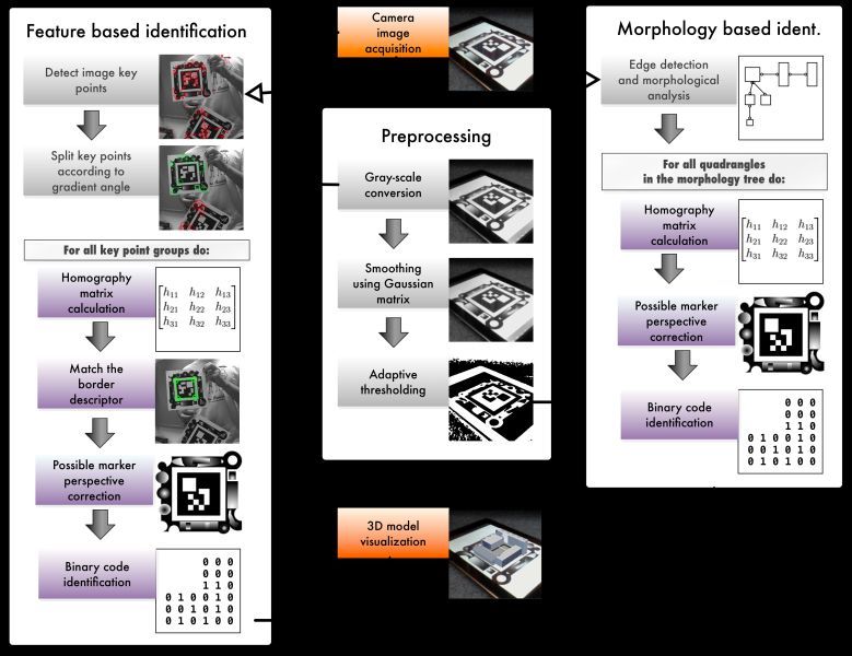
Figure 1 – Marker recognition scheme that outlines the basic principle of both implemented methods. Used methods are adaptively switched during the recognition process.
After detection and identification of all markers in a camera image using the method described above, our engine tries to identify occluded stationary markers. The engine detects all features with high eigenvalue (see [12], implemented in OpenCV method goodFeaturesToTrack). Further, the method FindCornerSubPix is used to get refined feature locations with subpixel accuracy. In our method, these features are compared with marker corners that were detected in a previous camera frame. If a previously stored corner and a detected feature lie in a same 3px window, there is a high possibility that detected feature is a corner of occluded marker. The window is only 3 px wide, therefore, the probability of mismatch is extremely low. The main advantage of this feature detection approach is that there is no need for detection of line occlusions. Whole process can be described by following algorithm:
IF previously found marker is not detected:
find features with high eigenvalue
FOR each previously detected marker corner:
compare all features against the corner
IF previously detected marker corner and a feature lie in a 3px window:
mark the feature as a corner of occluded marker
FOR each found occluded marker:
compute transformation matrix
We found that this approach can be also used for elimination of problems with sudden lighting conditions changes. These lighting changes may disturb the detection process, but once the stationary marker is found, the detection process is independent of the light conditions.
In previous work [10] we have developed a hybrid detection method { SURF-Golay (S-G) { in which the marker template is divided into two parts: the marker border and marker content (Fig. 2. These two parts of a template may be combined independently. Marker content is composed solely of a Golay code image. Marker border is composed of arbitrary geometrical shapes. Only marker content is used for marker identification.
The first step of marker matching is to discover keypoints in the processed image using standard SURF detector [1]. Then descriptor vectors for each keypoint are found using SURF feature extractor. These vectors are matched by computing Euclidean distance between each pair of points. Also we use symmetric matching filter [7] to improve the matched keypoint pairs. Further, we filter the set of keypoints by applying an angle filter [10]. For each set of points detected by angle filter we compute homography matrix to correct perspective deformations.
By application of the homography transformation to the image the Golay code can be identified. The perspectively corrected image is cropped and processed by the Golay code detector. If a Golay code is found it means that the whole marker is identified. This identification introduces very important feedback for the SURF marker detection. Given the reliability of the Golay detector, false positives are almost impossible. Therefore, if the code is identified, we can be sure it is one of searched markers. It also means that the homography was computed correctly. This is an important improvement of detection reliability which is not used in other methods such as [13]. Generally speaking, unreliable identification of markers is one of the key drawbacks of feature based methods.
The S-G detection method is focused on robustness against marker occlusions. Its robustness is established by the usage of the SURF detector which searches the image for keypoints. These keypoints are evenly distributed on the marker border. Although highly asymmetrical, the marker border is designed so that all parts are equally important. Therefore it does not matter which part (any corner or side) of the marker is occluded. Dealing with occlusions on the marker border is inherently natural for this detection method and therefore no special processing is required. Marker content (Golay error correction code) is slightly more sensitive to occlusions, but still capable of dealing with realistic occlusions (fingers, pointers). The ability of S-G detection method to deal with occlusions is independent on the movement of the marker; it works the same way for stationary and non-stationary markers.
Obviously, the two methods described above are complementary. Therefore a adaptive switching method has been designed. Since the implemented application works in real-time, the detection methods used are focused on performance. The main application thread loads a camera image and sends it to the visualization engine.
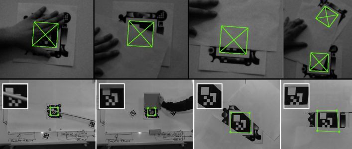
Figure 2: Occlusions. Examples of corner based occluded marker detection are shown on the first row. The second row presents S-G method capabilities of detecting occluded markers. Last two images show highly occluded markers (up to 60 %).
Therefore, the camera stream frame rate is independent on the tracking performance. Although a small lag between marker movement and 3D object adjustment may be observable, overall usability was increased. The framerate of background rendering is approx. 30 fps on a reference machine using OpenGL (Intel Core i5 1.7 GHz, 4 GB of RAM, SSD, Intel HD Graphics 3000 384 MB).
Simultaneously, the morphology based detection thread loads last camera image and starts a marker iden- tification process (approx. 14 fps with one detected marker). As soon as the markers are found, the list of detected markers is provided to the visualization engine and 3D model positions are updated. This process then repeats for subsequent video frames. The list of detected markers is also compared with the list of markers found in previous frame. In case a previously detected marker is missing in current frame, a new detection thread is started. This thread applies the S-G detection method which allows finding even a significantly occluded marker.
The following camera frame is again analysed with the morphology based method in the first place even though there is a high probability that the marker is still occluded. This may seem to be a waste of resources, but there is a problem to formulate a condition that allows the application to reliably switch back on fast tracking method. Nevertheless, the time of potentially unnecessary morphology based analysis is less than 10 % of the overall time consumption (the S-G performance is approx. 2 fps). The whole detection process is outlined in Fig. 1.
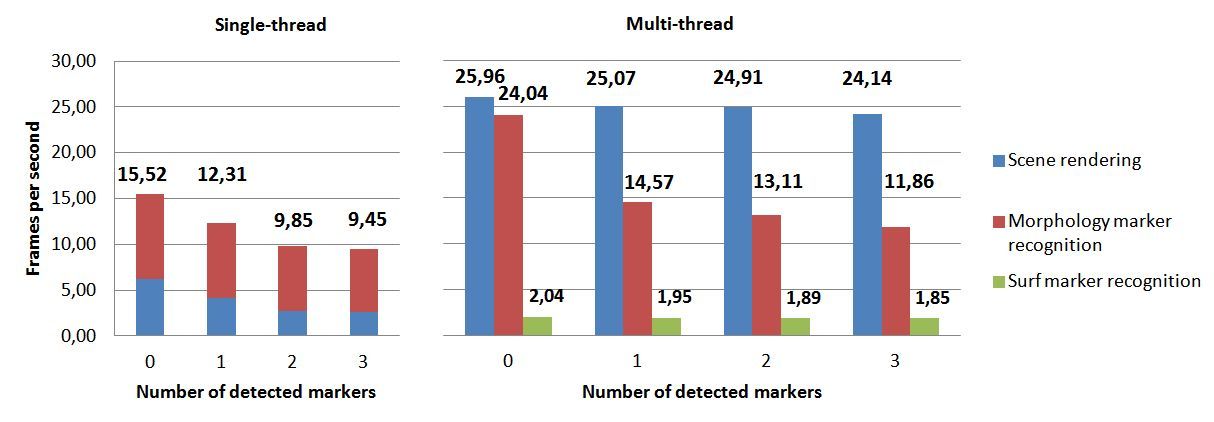
Figure 3: Comparison of the single and multi-thread implementation. Higher values signify higher framerate. Parallel rendering and marker recognition substantially improved application performance. The number of processed markers has just minor effeect on the recognition framerate.
The objective of this article was to present a marker detection approach that is composed of two detection methods { edge based marker detection and our S-G detection. Each of these methods has its advantages and disadvantages (especially performance and resistance to occlusions). We therefore proposed and implemented an adaptive solution that switches the detection method according to various conditions.
One of the key problems is substantial marker occlusion. Marker occlusions may occur due to a number of reasons { physical occlusion of the marker, light re ections, light interference, sudden lighting changes, camera noise etc. Implemented morphology based method is fast and precise with only minor disturbing effeects such as jitter of the 3D object. In case it is supplemented by our new method based on tracking features within a 3px window, it can deal with substantial occlusions. However, two conditions must be fulfilled: marker must be stationary (therefore nor camera, nor the marker can move) and at least one corner must be visible. Especially the first prerequisite is the key limitation of this solution.
On the contrary, the SURF based method is naturally resistant to occlusions. Moreover, our extension of this method by the usage of the Golay error correction code allows to identify high number of markers within the camera image. Therefore we designed a method that uses the S-G algorithm as a backup solution for the case when the morphology based method fails. Nevertheless, its performance is significantly lower.
Presented adaptive switching brings substantial usability improvement. The marker recognition system is adaptable to platforms with limited resources, e.g. various mobile devices (see [18] or [14]). Moreover, this adaptive detection method switching approach allows creating more complex tracking strategies. For example, performance effeective tracking can be used. Fast detection analyses the whole camera image, complementary precise method searches only within regions of interest around previously found markers. The goal is to minimize the time consumption as well as maximize the precision. Further, a completely new object recognition methods that are usually not suitable for discussed real-time applications can be used (e.g. neural networks) [15].
Acknowledgement: This paper is written as a part of a solution of project IGA FBE MENDELU 7/2012 and research plan FBE MENDELU: MSM 6215648904.
[1] Bay, H., Tuytelaars, T., Gool, L. V.: Surf: Speeded up robust features. In ECCV, 2006, pp. 404-417.
[2] Bergamasco, F., Albarelli, A., Rodola, E., Torsello A.: RUNE-Tag: a High Accuracy Fiducial Marker with
Strong Occlusion Resilience. Computer Vision and Pattern Recognition { CVPR, 2011. pp. 113-120.
[3] Billinghurst, M., Kato, H.: Collaborative augmented reality. Comm. of the ACM 45, 7, pp. 64-70. 2002.
[4] Fiala, M.: ARTag, a fiducial marker system using digital techniques. Computer Vision and Pattern Recog-
nition. June 2005, vol. 2, pp. 590-596.
[5] Kato, H. Tachibana, K. Billinghurst, M. and Grafe, M.: A registration method based on texture tracking
using ARToolKit, In Augmented Reality Toolkit Workshop, pp. 77-85, 2003.
[6] Kroeker, Kirk L.: Mainstreaming augmented reality. Comm. of the ACM 53, 7, pp. 19-21. ACM, 2010.
[7] Laganiere, R.: OpenCV 2 Computer Vision Application Programming Cookbook. Packt Publishing, 2011.
[8] Lowe, D. G.: Distinctive image features from scale-invariant keypoints. IJCV, 60, 2004, pp. 91-110.
[9] Khan, W. A. Raouf, A. Cheng, K.: Virtual Manufacturing. pp. 819, Springer, 2011.
[10] Prochazka, D. Stencl, M. Popelka, O. Stastny, J.: Mobile Augmented Reality Applications. Mendel 2011:
17th International Conference on Soft Computing. Brno University of Technology, 2011, pp. 469-476.
[11] Russ, J. C.: The Image Processing Handbook, Sixth Edition. CRC Press, USA 2011. 885 Pages. ISBN
9781439840450.
[12] Shi, J., Tomasi, C.: Good Features to Track. Computer Vision and Pattern Recognition, 1994. pp. 593-600.
[13] Seo, J., Shim, J., Choi, J. H., Park, J., Han, T.: Enhancing Marker-Based AR Technology. Virtual and
Mixed Reality - New Trends, Lecture Notes in Computer Science, 2011. Volume 6773/2011, pp. 97-104,
[14] Stastny, J. Prochazka, D. Koubek, T. Landa, J.: Augmented reality usage for prototyping speed up. Acta
univ. agric. et silvic. Mendel. Brun., 2011, LIX, No. 2.
[15] Skorpil, V. and Stastny, J.: Comparison Methods for Object Recognition. In Proceedings of the 13th
WSEAS International Conference on Systems. Rhodos, Greece, 2009. pp. 607-610.
[16] Szeliski, R.: Computer Vision: Algorithms and Applications. London: Springer 2011.
[17] Tuytelaars, T., Mikolajczyk, K.: Local invariant feature detectors: A survey. FnT Computer Graphics and
Vision, pp. 177-280. 2008.
[18] Wagner, D., Reitmayr, G., Mulloni, A., Drummond, T., and Schmalstieg, D.: Real-Time Detection and
Tracking for Augmented Reality on Mobile Phones. IEEE Transactions on Visualization and Computer
Graphics, pp. 355-368, IEEE, May/June, 2010.