
Abstract
Maintenance
- Introduction
- Review of researches and development
- 1. Purposes and research problems
- 2. The main questions which have to be resolved in this work
- 3. Stand structure for research of digital systems
- 4. Review of elements of power part of the stand
- 4.1 DC drive
- 4.2 Break modes in DC drive
- 4.3 Thyristor converter as element SCED
- 4.4 Features of reversive thyristor converters
- 5. Control systems
- 5.1 Closed-loop system
- 5.2 Digital control system with РС use
- 5.3 Digital control system ABB DCS 800
- Conclusion
- References
Introduction
In it is modern the world an integral part there were digital control systems. At this stage of development they actively develop in areas of automation and control systems of industrial technological facilities. Without them it is now difficult to present precision, power effective, high-quality and safe work of various industrial facilities. For expansion and increase of knowledge for students requires development of the experimental stand for studying of such systems
Review of researches and development
Because now complexity of systems (algorithms) of control increased, therefore, creation of experimental installation for check of algorithm control becomes complicated. In most cases, in works about research of different system represent only results of mathematical modeling. Mathematical modeling gives the chance to us, without having physical object to study its properties that is the first and important step for further studying, however experimental installation with use of physical model is the main stage in design of new algorithms and control systems. Allows to reveal some features which at mathematical modeling aren't notable, but can have a great impact on control quality.
In recent years in the sphere of information technologies interest to concept as "Virtual educational laboratory" (VEL) in relation to the technical sphere began to be shown.
The term VEL can be applied to modern ways of research processes which proceed to EMS which basis on the mathematical description and the model based on it. Mathematical modeling is carried out with use of applied programs. Among foreign companies, leading positions in development of applied programs are taken by such companies as MathWorks, MicroSim, Cadence Design Systems, Interactive Image Technologies, National Instruments, Spectrum Software, MathSoft, Wolfram Research. When developing stands for interaction of mathematical model and physical mainly use MATLAB, Mathcad, LabVIEW. Each package differs from each other on the structure and mathematical opportunities.
On electric drive departmens in Ukraine laboratory experimental installations which can combine object researches, both at the level of modeling, and at the level of physical experiment were created. In these works [2 - 6] the complex of various actions was developed:
- Check of analytical methods, on the experimental installation, allowing to realize a digital control system of position DC electric drive in real time [6]
- Use station of fast modeling which allows to make modeling with use of virtual object control, i.e. algorithm of control is fulfilled not on real installation, and on internal model (the engine, the converter) [2]
- Realization, approbations and researches new algorithms of identification, controlt and supervision of various electromechanical systems with difficult parametrical and functionally uncertain objects [3]
- Realization in installation "mechanism" of imitation various technological processes [4]
- Use of prepacked electric drives with expansion and complication of standard systems which were put by the manufacurer with use of additional modules [3]
- Possibility of imitation of normal, preemergency and emergency work operation [5]
- Supervision over a condition of system as a whole and beyond its separate elements [3, 5]
Algorithms of control become unified and a difference between settings of the drive of direct and alternating current not such essential as were before realization of control systems in a digital form.
The realized projects have merits and demerits. As a matter of experience creations various experimental installations in different HIGHER EDUCATION INSTITUTIONS in our country, considering all merits and demerits, development of the laboratory stand for research various digital systems of automatic control which based on DC electric drive in real time with possibility of control from various programmable complexes is conducted.
1. Purposes and research problems
The purpose – creations of the laboratory stand for research various digital systems of automatic control which based on DC electric drive in real time with possibility control from various programmable complexes with use diverse types of converting equipment. Research have to be made in interrelation with modified schemes and operating modes of the electric drive, and as with use of the latest converting equipment.
2. The main questions which have to be resolved in this work:
- The analysis of existing decisions in the field of control systems and converting equipment
- Creations of own laboratory stand for scientific and practical researches
- Demonstration possible methods of changeing structure of system and algorithms control of the prepacked electric drive
- Development system automatic control by the electric drive in real time with use of digital systems
- Modeling processes in the created system of regulation
3. Stand structure for research of digital systems
The laboratory stand unites in itself the following components: two engines of the direct current, two prepacked thyristor converters (2х quadrant) ABB DCS 800, with possibility of control under the industrial network Profibus-DP protocol; two converters BTU series (4х quadrant), with probability control both from digital control systems, and from analog schemes; the PC computer with use of high-speed PC a compatible board ADC/DAC 5710-1 Octagon systems, and computer for possible more precition setup of the DCS 800 converter; two tacho generators for speed rotation measurement; galvanic outcomes; measurment analog devices on the panel for measurement and voltage regulators; Vipa Speed 7 – 314ST.
Figure 1 – Schematic diagram of the stand
(animation: 6 frames, 7 cycles, 260 kilobytes)
Figure 2 – ABB DCS 800
4. Review of elements of power part of the stand
4.1 DC drive
Direct current drive – the electric machine intended for transformation electric energy of a direct current in mechanical energy (engine) or for the return transformation (generator).
Principle of action. The machine of a direct current has the winding of the excitement located on obviously expressed poles. On a winding the direct current (excitement current), creating a magnetic field excitement proceeds. On a rotor the two-layer winding in which at rotation of a rotor the EMF variable is induced is located. By means of the mechanical converter of energy – a collector, this EMF becomes straight. At the set direction of rotation of an armature the EMF direction, induced in its conductors depends on under what pole there is a conductor therefore in all conductors located under one pole, the EMF direction identical and remains such irrespective of rotation frequency.
Structurally machine of a direct current consists of a stator (on which there is an excitement winding), a rotor (armature) and the brush-collector device (transformation of the EMF variable to constant voltage or contrary).
On a way of electric windings connection engines of a direct current happen the independent, parallel, consecutive and mixed excitement. The way of windings connection influences by sight static and dynamic characteristics.
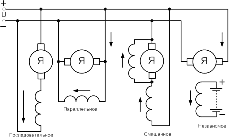
Figure 3 – Winding connection in DC drive
The greatest distribution was gained by DC drive with independent excitement. Their distinctive feature is possibility of separate control of current on an armature (control in the first zone, is lower than idling speed) and a magnetic flux (in the second zone, idling speeds are higher). Using the equation of an armature chain, having expressed from it EMF and having divided into work of a magnetic flux and a constructive constant, we will receive the equation of the mechanical static characteristic:
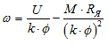
The speed of the engine can be changed in three ways – change of voltage of an armature, change of a magnetic flux, introduction of additional resistance. Regulation by means of introduction of additional resistance extremely inefficiently, in view of reduction of efficiency and need for the powerful resistors demanding good cooling. Therefore this way of regulation won't be considered. Thus it is possible to notice that characteristics the fields received by weakening have various inflexibility which is less than at the natural mechanical characteristic.
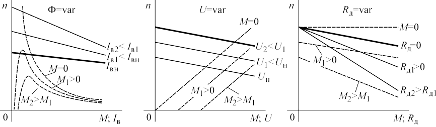
Figure 4 – Speed regulation in DC drive
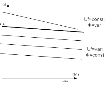
Figure 5 – Speed regulation in first and second zone
The machine of a direct current can work as engine (speed of the engine lower than idling speed), and in generating (idling speeds are higher) mode, giving energy to a network. The reverse is carried out of change of the direction of armature current, or change direction of excitement current.
4.2 Break modes in DC drive
Braking can be carried out the next ways:
- Generating braking
- Braking by opposed action
- Dynamic breaking
Generating braking – braking is applied upon transition to lower speed. Voltage fall, speed and EMF can't instantly change, it leads that current changes the direction and starts proceeding from the engine to voltage source.
Braking by opposed action it is made by switching of polarity of tension of an armature and injection in its chain of additional resistance. It is necessary to disconnect the engine and, depending on that what moment of loading is enclosed, to impose a mechanical brake.
Dynamic breaking it is carried out by short circuit of an armature on additional resistance. At the active moment of loading it is necessary to impose also a mechanical brake at a zero speed.
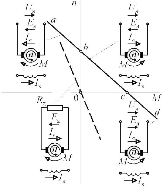
Figure 6 – Breaking (ab – Generating braking, cd – Braking by opposed action, dotted line – Dynamic breaking)
4.3 Thyristor converter as element SCED
The structure of modern TC includes the following elements:
- Transformer or current-limiting reactor. The transformer serves for coordination on engine voltage with a network, the reactor – for restriction speed increase of direct current through a tiristor.
- The power scheme TC providing transformation a sort of current from one look to another.
- SIPC which provides transformation of a continuous entrance signal Uу received from regulation system, to sequence operating impulses on tiristor.
- The switching and protective equipment (a control unit and protection CUP), providing connection of the converter to a network and to loading, disconnection TC from a network and emergency braking of the engine, and also various protection of the engine.
- Besides, the smoothing reactor (throttle) intended for improvement form of straightened current and restriction a zone of faltering currents can be a part of the thyristor converter.
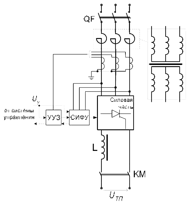
Figure 7 – The simplified function scheme ТC
The main link of TC is the power scheme. Power schemes of TC share on zero and bridge. The main type of schemes in DC drive is the bridge scheme. Zero schemes are applied rather seldom – to power supply of low-power engines and excitement chains. The most widespread three-phase irreversive schemes.
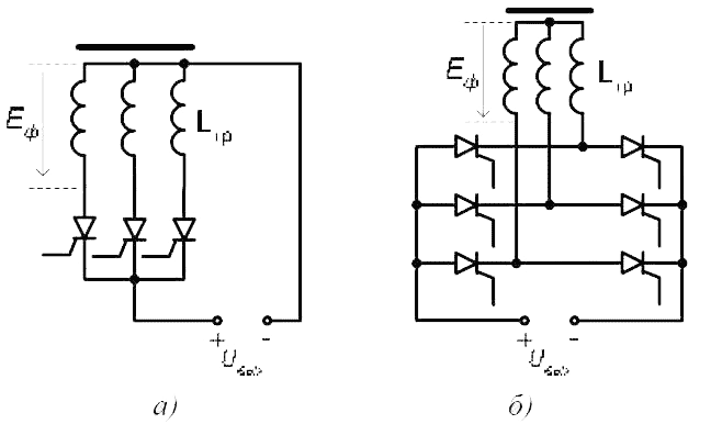
Figure 8 – Power schemes of the three-phase irreversive ТC: а – zero; b – bridge.
Important indicators of power TC schemes are:
- pulses of the straightened voltagem, equal to number of phases TC (for the three-phase bridge scheme m=6, for three-phase zero scheme m=3);
- scheme coefficient – the relation of the maximum straightened EMF Ed0 to operating valueEф phase EMF of the network feeding TC (if TC is connected to a network via the transformer, as voltage of a network the EMF of a secondary winding of the transformer is considered):
Num. values: ksh=2,34 – for bridge scheme, ksh=1,17 – for zero scheme.
4.4 Features of reversive thyristor converters
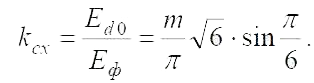
Change of polarity voltage enclosed to the engine, involves corresponding change of the direction course of current. As the thyristor has unipolar conductivity, the reversal of current can be carried out:
- by means of a contactor reverser (it is applied to low-responsible low power drives)
- by means of installation two sets of thyristor, each of which feeds loading with current of opposite polarity
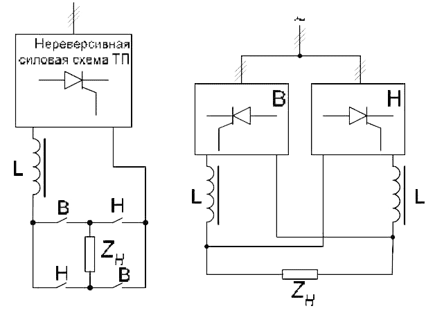
Figure 9 – Reversal scheme TC
At realization of the second way two schemes – cross and counter-parallel are possible.
Counter-parallel scheme are found the greatest distribution at reversive thyristor in DC drive as causes the smaller rated capacity of TC and the best mass-dimensional indicators.
On a way of control distinguish reversive TC with a separate and combined control.
Now combined control of TC groups is used in rather exceptional cases of realization the special drives which operating modes are connected with course of small currents and frequent change of polarity current. At a combined control two SIPC (for each group) carry out shift of operating impulses in opposite directions, and impulses move continuously on thyristor of both groups. One group works in a rectifier mode (α<90°), second – in inverter mode (β<90°). The carrying-out condition of groups gates and the direction of current loading is defined by a ratio of EMF converters and loadings.
Shortcomings of a voltage control:
- because of course leveling current additional current loading of TC and a network takes place, losses increase.
- emergence s.c is possible between sets of gates;
- needs to use more expensive transformers with two secondary windings and leveling reactors.
All modern serial TC are issued with combined control at which unlocking impulses move on thyristor of only one group, and impulses of the second are thus blocked. Switching groups possibly only on a signal from regulation system at zero current in a loading chain. The signal on switching groups gates is developed by means of the logic switching unit (LSU).
The LPU device forms logical signals for work of thyristor groups depending on a signal i0,arriving from the zero current sensor (SCZ), and also a logical signal demanded on direction of current is, regulation received from system (specifies, which group has to work).
When switching groups seek to provide that the EMF included group would be equal to the EMF of disconnected group, – there will be no current throw provided that when switching and process of falling off of current will be accelerated. For this purpose most often use the switch characteristics (SC) which at the same time with switching of groups changes polarity of a signal Uy on the opposite.
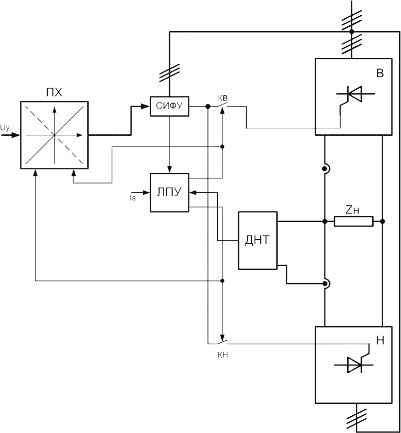
Figure 10 – Function sheme of TC with separate controle.
5. Control systems
5.1 Closed-loop system
Apparently from static mechanical characteristics, with moment growth angular speed decreases that is inadmissible in devices where exact regulation of speed and providing the identical moment at different speeds is necessary. To these purposes apply the closed systems of regulation with feedback on the speed or EMF/voltage which compensate sag on speed by a raising voltage armature or weakening of a magnetic field, depending on a regulation zone.
Regulation of angular speed on an armature chain. We will write down the equation of an armature chain, the equation of the moment, EMF and also the second law of Newton for a rotary motion, and, having passed into an operator form record, we will find transfer functions and we will make the block diagram.
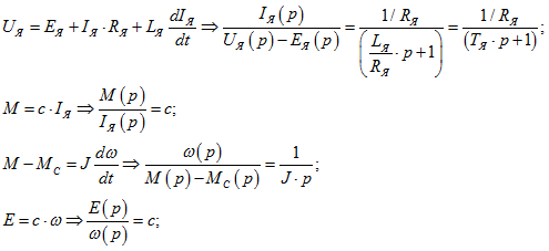
Counting current and speed regulators, we neglect influence counter-EMF, including its insignificant.
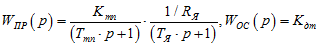
Control essence – regulator realization with TF of the return to product TF of a direct branch and a branch of a feedback of a contour regulation.
For a current contour:
But as the lag effect of the converter can't be compensated, we exclude it from synthesis. As at a contour of current there is an indignation, and it needs be executed astatic, therefore, the regulator of current has to be type PI, but, proceeding from above told, we receive PD TF.
Having increased received TF by the integrator with time constant Tm we will receive the required TF:
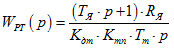
Transfer function of overall current contour:
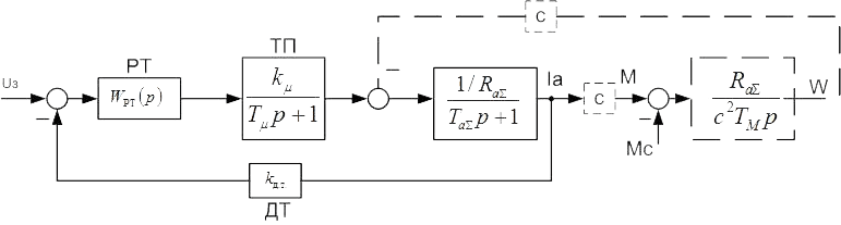
Figure 11 – Block diagram of a regulation current contour
Tuning a contour speed regulation is similarly performed. As a result we receive TF of the speed regulator and the block diagram of all system entirely:
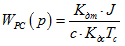
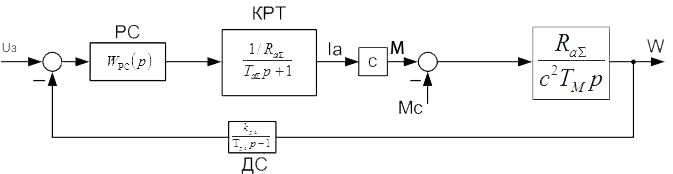
Figure 12 –Block diagram of a regulation speed contour
5.2 Digital control system with РС use
Modern control systems of electric motors are under construction with use of digital equipment. In recent years in all industries microprocessors for digital processing of signals were widely adopted – DSP (Digital Signal Processors).
The main difference of DSP from the ordinary processor is the high speed of performance of X=AB+C operations (for one step). It is known that the algorithm of control an electric motor mainly consists arithmetic operations of multiplication and addition, and consequently DSP application in control systems of electric drives extremely expediently. DSP contain in the structure besides standard blocks for any microprocessor the blocks, providing control of the power converter (PWM the modulator), collection information about a condition of system (ADC, Encoder), etc.
The digital controler has to possess the demanded computing power for calculation and delivery signals control, and also to have the necessary interface for control system in real time.
For creation of own digital control system we use the PC computer with use of high-speed PC combined board of the ADC/DAC expansion 5710 Octagon systems.
Octagon 5710 represents ADC board with high resolution on which devices input-output discrete signals also contain.
The analog part of a board allows to make measurements with a frequency of 70000 measurements a second. Initialization of the converter is carried out or under control board calculations (a processor board) or by means of the 5710 counter/timer located on a board. The counter/timer can be used for performance of temporary measurements general purpose or PWM-signal generation.
To a 5710 board can be connected 16 unipolar or 8 differential analog signals. Also there are 2 analog output channel and allows to work with 19 discrete lines of input-output.
Figure 13 – 5710 Octagon systems
For control system will be used both analog inputs and outputs, and digital once. Analog for reading coordinates which change during time (such as: Ia current, Ie current, speed rotation), and as discrete for a prediscretion various protection.
The control system is created on the basis systems of the subordinated regulation and executed in a MATLAB package with Simulink use, transformed for use in the environment QNX where it is provided editing and record parameters of studied object interesting us. QNX an operating system of a real time. It is allocated most with a totality of tools to which the user got used in DOS or UNIX, provides all integral components system real time: multitasking, scheduling of programs on the basis priorities and fast switching of a context.
5.3 Digital control system ABB DCS 800
The ABB DCS 800 converter is prepackted. The prepackted electric drive is the electric drive completed at manufacturer with all knots, necessary for its functioning.
When using this converter we are haveing the chance to change various parametrs(about 1000) for hanging its energy efficiency and quality of demanded characteristics.
Example of influence various parameters on a speed control:
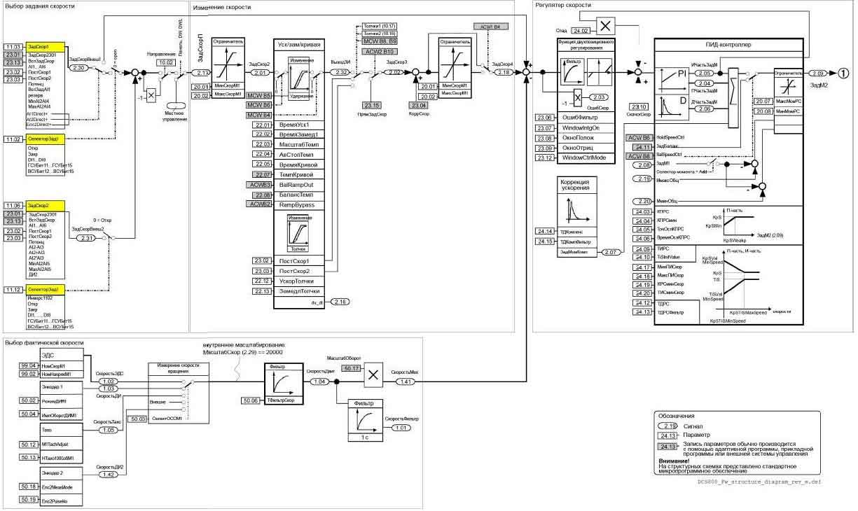
Figure 14 – Block scheme of a speed control
There are various control options DCS 800 и настройки:
- Control with help of front panel
- Control and monitoring with help of 5710
- Control and monitoring with help of software Drivewindow 2
- Control with CoDeSys software
- Control with industrial comunication networks Profibus-DP and PLC series 300 (Siemens or Vipa)
Для стенда будет применено помимо, управления и мониторинга с использованием высокоскоростной платы АЦП/ЦАП 5710 и параметрирования и мониторинга с использованием программного обеспечения Drivewindow 2, использования промышленного протокола передачи информации типа Profibus-DP
Profibus DP (Decentralized Peripheral) — the protocol focused on ensuring high-speed data exchange between:
- automation systems (master DP devices)
- devices of the distributed input-output (slave DP devices)
The Profibus network consists of master and slave stations. The master station can control the bus, that is can transfer messages (without remote inquiries) when it has the right for it (that is when it has a marker). The slave station can recognize only the received messages or transfer data after the corresponding inquiry. The marker circulates in the logical ring consisting of leading devices. If the network consists only of one master, the marker isn't transferred (the master-slave system in that case is in pure form realized).
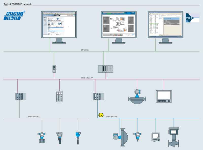
Figure 15 – Example of Profibus use
With PLC application we can not only operate the electric drive, but also there is an opportunity for all of possible statements and realization of technical tasks that will allow us to expand functionality the stand and to raise level of application of various control systems for more best training for students.
Conclusion
Final end: December, 2014. The full text of work and materials on a subject can be received at the author or his head after the specified date. This part of the paper the exclusively survey. Further work will be directed on a pilot study and completion of available results in the sphere of digital control systems.
References
- Пересада С.М., Ковбаса С.Н. Цифровые системы управления электроприводом [электронный ресурс] – Режим доступа:http://www.el-drives.com
- Пересада С.М., Ковбаса С.Н. Станция быстрого моделирования алгоритмов управления электроприводом [электронный ресурс] - Режим доступа:www.el-drives.com
- Полилов Е.В., Батрак А.М., Руднев Е.С., Скорик С.П., Горелов П.В. Исследовательский стенд для апробации алгоритмов Управления сложными электромеханическими системами // Електротехн. та комп'ют. системи. - 2011. - Вип. 3. - С. 481-487. - Библиогр.: 14 назв. - рус.
- Толочко О.И., Розкаряка П.И., Горобец Н.М. К вопросу об изменении типовых структур цифровых систем управления комплектными электроприводами // Наукові праці Донецького національного технічного університету. Серія: “Електротехніка і енергетика”, випуск 10 (180). - Донецьк: ДВНЗ «ДонНТУ», 2011. – C. 188-193
- Чорний О.П., Кравець О.М., Неборак О.І. Віртуальний комплекс «Система електроприводу генератор-двигун з електромашинним підсилювачем» // Електромеханічні і енергозберігаючі системи. – Вип. 3(11). – Кременчук: КДПУ им. М.Остроградского, 2010. – С. 107-111.
- Толочко О.И., Коцегуб П.Х., Розкаряка П.И Реализация алгоритмов цифрового управления позиционным электроприводом постоянного тока // Вісник Кременчуцького державного політехнічного університету імені Михайла Остроградського. Вип.3(44):Ч.1 . 2007 . 178 с. : іл. - С. 18-20.
- Чиликин М.Г., Сандлер А.С. Общий курс электропривода: Учебник для вузов. - 6-е изд., доп. и перераб. - М.: Энергоиздат, 1981. - 576 с.
- Алексеев К.Б., Палагута К.А. Микроконтроллерное управление электроприводом // Учебное пособие. - М.: МГИУ, 2008. - 298 с.
- Чекавский Г.С. Конспект лекция по СУЭП, ДонНТУ, каф. ЭАПУ, 2012 г.
- Усольцев А.А. Общая электротехника // Учебное пособие. СПб.: СПбГУ ИТМО, 2009. - 301 с.