
The abstract on a theme of final work
Contents
- Introduction
- 1. The urgency of work
- 2. Goal and tasks of research
- 3. Classification and purpose of stamps
- 4. The basic strategy milling while processing molds
- 5. Prospects and advantages of introduction of modern cutting tools and modern processing strategies
- Preliminary conclusions
- The list of the used literature
Introduction
more attention is paid to the development and improvement of treatment of cavities stamps with the removal of the relatively small layers of metal, high-performance processing methods, modern cutting tools, and application of advanced processing strategies, in the framework of modern, safe and high-tech production, while creating high-quality products with the latest technology.
The constant development of technology at the modern stage requires the use of parts of different designs, shapes, sizes, which are fairly thin walls (to save material and facilitate the design in General), the most optimal way to retrieve data products it stamping. Now their number significantly increased in the total mass of parts subjected to machining.
1. The urgency of work
Currently, production of stamps is gaining momentum. The main role is played: order fulfillment, manufacturing cost of a stamp, high quality products, and of course the use of new trends in treatment – which significantly increases the quality and interest to the manufacturer.
One of the key emerging industries, where the most important application of stamps – the automotive industry. The modern consumer car does not want to see the lack of design and simplicity of lines in the form of right angles.
At this stage of development of the automotive industry – it's important to realize in the metal work of the designer. This particularly applies to body panels. Their production is impossible without the use of high-tech stamps. Every year the number of vehicles is increasing on average by 5-10%.
| Country | 1980 | 1990 | 2000 | 2010 | 2011 | Height(time) | |
| 1 | China | 222 | 509 | 2069 | 18264 | 184418 | 82,9 |
| 2 | USA | 8009 | 9782 | 12800 | 7761 | 8653 | 1,1 |
| 3 | Japan | 11042 | 13487 | 10140 | 9625 | 8398 | 0,8 |
| 4 | Germany | 3978 | 4976 | 5526 | 5906 | 6311 | 11,6 |
| 5 | South Korea | 123 | 1322 | 3144 | 4272 | 4657 | 37,9 |
| 6 | India | 114 | 362 | 801 | 3536 | 3936 | 34,5 |
| 7 | Brazil | 1165 | 914 | 1681 | 3382 | 3406 | 2,9 |
| 8 | Mexico | 490 | 820 | 1935 | 2345 | 2680 | 5,5 |
| 9 | Spain | 1181 | 2053 | 3032 | 2388 | 2354 | 2,0 |
| 10 | France | 3378 | 3769 | 3348 | 2228 | 2295 | 0,7 |
| 11 | Canada | 1369 | 1947 | 2962 | 2071 | 2134 | 1,6 |
| 12 | Russia | 1884 | 1074 | 1202 | 1403 | 1988 | 1,05 |
| 13 | Iran | 161 | 45 | 141 | 1599 | 1648 | 10,2 |
| 14 | Great Britain | 1312 | 1565 | 1813 | 1393 | 1464 | 1,1 |
| 15 | Thailand | 73 | 305 | 325 | 1644 | 1458 | 20,0 |
And every 5-6 years, every model has a new generation, every 2-3 years is restyling – all these measures contribute to pre-order the new stamps, with the changed configuration of the cavity of the stamp, which in turn gives continuous loading of production of stamps.
Therefore, high-performance production methods stamps are promising and relevant[1, 2].
2. Goal and tasks of research
The aim of this work is: the processing capacity of cavities dies in a flexible automated production, through the use of modern cutting tools and advanced processing strategies. To achieve this goal in master's degree work the following tasks were defined:
- To carry out the analysis of literary sources and directories to identify the most productive and resistant cutting tools.
- Develop your own strategy of treatment and to evaluate their performance based on a possible reduction of the volume of waste metal.
- To develop strategies processing and cutting tools.
- Savings when implementing these methods.
3. Classification stamps and their functions
The stamp – is a tool intended to give details of a given configuration by plastic deformation of the workpiece or split it into parts. For each part requires its own stamp[3].
Design it depends on the type of procurement (long or flats), type of machines used for stamping (hammer, press etc), the nature of the operations, the seriation of production, etc.
Is intended to give the details of a given configuration by plastic deformation of the workpiece or split it into parts. For each part requires its own stamp.
Classified stamps on technological and design features.
To process include: operation – cutting, bending, stretching forth; the degree of complexity of operations (combining operations). To constructive signs include: ways of interface working parts, fixing of preparations, methods of collection and removal of products.
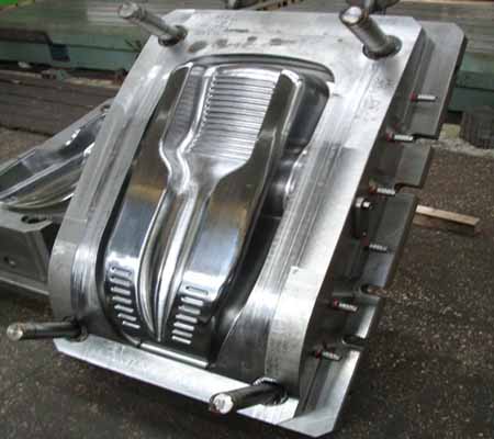
Figure 3.1 – Stamp cavity
Depending on the functions performed in stamps see the details of technological and constructive purposes. Details of technological purpose – it's the details that change the shape of the workpiece, i.e. matrix, punch and parts, locking, stimulating and remove products. Details of constructive purpose – those with which the stamp is associated press, details, providing interface working parts and their fastening, – plates, shanks, speakers, bushings, bolts and pins.
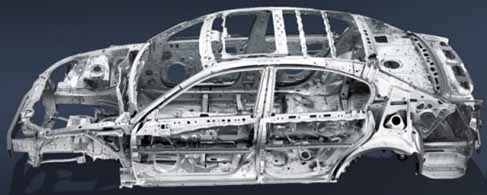
Figure 3.2 – Example of use of stamped details in automotive industry
All stamps are required, providing quality parts, high performance, durability, convenience and safety of operation, easy installation and removal of stamps. Stamps for cold stamping are produced from steel grades: У8—У13, H, H9, 9ХС, HG and other
Name stamps determine that they execute operations: cutting produce blanking dies, the hood and exhaust, bending machines, and so on Fundamental difference of these stamps is the design of the details of technological purpose – the punch and die[4, 5, 6].
The working part of a punch cutting of a stamp matches the shape of the contour cutting, and the matrix of the stamp has a hole shape cutting. Preparation for cutting is a strip of material.
Flexible procurement using bending dies widely used in the manufacture of various products. Depending on the shape of parts flexible procurement can be one-, two - and multi-angular equally, end, etc., Flexible metal is the result of elastoplastic deformation occurring varies with each of the parties flexible procurement. For bending of parts channel profile, especially with curved axis or different width, apply bending dies wedge type. Flexible pipes and thin-walled profiles also produced bending dies.
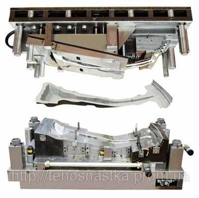
Figure 3.3 – Stamping process
Bending stamps is a great variety of designs depending on the form of stamping parts and the availability of the Clamping device. The working part of the Punch is directed bulge given curvature, and matrix – parallel to punch the curvature of the surface. Stamping bending dies occurs without changing the thickness of stamping Catala.
Logging and perforation make sheet semifinished items used for formoizmeneniya operations sheet metal forming. By cutting formed the outer contour parts, punching a hole or notch. On the surface quality of the section distinguish between normal and fine cutting-punching. In the technological process are used, respectively, punches and punching dies.
Punching dies in principle do not differ from the cutting. The only difference is that harvesting for them is not the band, and cut the cake mix. Complex punching dies punched several holes, the result is a delicate figure. Stamping parts jewelry requires high precision and minimum waste of precious metal, So as separation of operations is applied sheet cutting and punching. Under a clear separation of metal cutting and punching dies give the chance to cut down and punching parts with clean cut surface. For sheet cutting matrix is produced with rounded or sharp edges or punch, which exceed the Hole matrix.
Finishing punching possible by punch with rounded edges. Hood can produce the parts from metal and materials thickness from 0.2 to 30 mm Hood is made on Cam, crank presses, Cree-vasopressinergic presses simple steps, crank presses double-acting hydraulic press and stamps of various types and designs.
The complexity of the process and method of drawing depend on the material and design of the manufactured parts 5 (aspect ratios characterizing the cross-section and height of the details, radii mates bottom, walls and flange configuration flange).
Exhaust stamps count compared to bending small number of typical designs, while the hood is the most difficult operation sheet metal forming. Punch exhaust stamp has a surface of the working part with a path and a bulge given curvature. On the matrix stamp negative punch elevation. Not always hood can be done in one pass, so the stamps can be: the first drawing, the second drawing, subsequent and final depending on the complexity of the hood.
To reduce passes with the aim of saving time stamp combines two operations, most often the hood with perforation. Such stamps called combined.
The stamping the simplest – most often represent a punch with the flat, smooth surface and a matrix that has deepened within the contour of semi-finished picture. Made engraving technique drawings may have a difficult relief, but the surface stamped parts should remain smooth – shells and irregularities. As a rule of embossed stamps do not form sloninov (blocs), punch such a stamp fitted directly to the press slide, and matrix – to the table.
Coordinate stamps – For more accurate punching holes is used coordinate punching on the coordinate-revolving press stamps. Open and closed stamps feature special guides devices (guides columns and slabs), which automatically adjusts and the steady movement of the punch. Modern technologies allow a simultaneous positional punch the hole series on different areas of the workpiece. Holes can have different shape and diametrically punching characterized by high quality parts and performance.
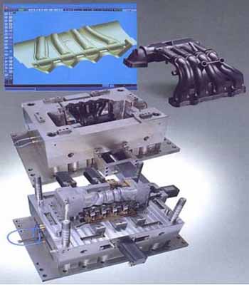
Figure 3.4 – Stamping process with a binding to 3D modeling
Chipping stamps – The process stumps is costly and involve significant noise effect. In serial production of castings from non-ferrous alloys is widespread process stumps bays and castings on presses in special chipping stamps.
Moulding dies – Stamps for relief moulding almost do not differ from bending dies with the workpiece clamp. They are, as a rule, with the guide columns. Widely spread are the stamps to perform operations flanging outer edges of parts and razbitosti holes.
The combined stamps – with the purpose of decrease in labor input of processes of stamping, reduction in cost of cost of stamped details and automation of works the combined stamping at which a number of simple operations is carried out in one stamp of the combined or consecutive action is applied. Stamps combined sovmeshchenno-consecutive action are applied also. Detail production in stamps of the combined action happens for one course of a press, without preparation movement. Transitions (operations) take place in the direction of press movement ram, and preparation is deformed consistently in process of ram movement (and consequently, and the top part of a stamp) down. Stamping is carried out both from separate preparation, and from a strip (tape). Usually stamps of the combined action are used for production of the details demanding from 2 to 4 operations at a thickness of material up to 5 mm. Possibility of combination depends on thickness of a stamped material and the detail sizes as at certain ratios of external and internal contours of a detail thickness of walls at punches and matrixes can turn out too small that will complicate their production and a thermal treatment[7, 8, 9].
The necessary parameters considered for the production of cavities stamps:
- Clear the drawing stamped part, material grade, dimensional tolerances, band width (tape).
- Model press and its characteristics (for installation of the stamp on the press).
- Type band feed (tape).
- The design of the stamp (stamp hard puller, with the upper clamp, combined actions).
- Whether the use of glue for fastening of punches and other details
4. The basic strategy milling while processing molds
Even the best tools will not be able to reach their potential if they are not used in conjunction with certain methods. Here are a few key strategies milling: thick shaving, end milling with circular flow, radial movement of a cutter at an angle to the processed surface, helical interpolation, positioning cutters, trade/fair milling of continuous cutting mills.
Correct the cutting effect and chipping can save time, money and ensure stable operation.
Key strategies milling while processing molds
Often each of us uses any available tool to perform the basic operations of milling and we are confident that we can do without the optimization process. Also we are familiar with the results of such approach: quality is bad and horrible sound that occurs during the processing of the corners. In addition, universal panacea” in the form of supply is disconnected only masks the real problem and minimizes performance.
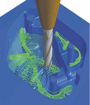
Figure 4.1 – Processing of a cavity of a stamp
Direct cutting mills
For bumping directly the process begins to be accompanied by a vibration. This vibration reducing the service life of the tool, poor surface quality, and the need to constantly monitor the process, so as to predict the duration of the service life of the tool becomes problematic.
Figure 4.2 shows the presence of the large chips when you tap cutters from the treated surface when it is rotated, causing the instrument is the maximum load. Then this effort quickly disappear, causing a slight fluctuations cutters, when the next plug-cutting plate in the holder of the cutting tool is included in the process, causing an increase efforts on the tool together with the load on the machine spindle bearings.
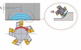
Figure 4.2 – The beginning of processing of a detail at direct incision of a mill – thick shaving at the exit
Start machining with direct cutting mills – thick shaving outlet.
Before the mill is fully seated in the workpiece, the output appears thick shaving, causing vibration damage to the cutting edges and cutting tool life.
All this is happening at a very high speed, causing the rattling sound, which persists until the Central centerline of the cutter does not pass the edge of the processed form. When the cutter will move to this position, the output will naturally appear thin shavings. You can easily see the difference in the thickness of lines in the farthest point on the right side.
Mechanical milling with circular flow
It is noteworthy that when using mechanical milling with circular flow (see figure 4.3) thin shavings will leave the cutter from the very beginning of the process, regardless of the position of the Central axial line cutters. In this case eliminated fluctuations tool because of the pressure and the emergence/relieve the load on the machine spindle bearings[10, 11].
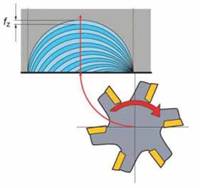
Figure 4.3 – The processing starts the part when the circular incision.
Circular incision allows to achieve the minimum thickness of a shaving outlet, reducing vibration and prolonging the service life of the tool.
Thus, the technique of mechanical milling with circular flow, not only resolves the issue of vibration, increasing the service life of the tool and the performance of the treatment process, but also reduces wear on the bearings of the machine spindle and makes the process more predictable. This predictability allows the machine operator to leave the office with full confidence that return will not have any surprises. Get thin shaving outlet also lets and radial movement of a cutter at an angle to the treated surface. If the mill starts processing at an angle of 20&grad;-30&grad; to the processed surface, there is the same effect as when the mechanical milling with a circular flow. This option is appropriate when using simplified programming of the machine.
Helical interpolation method
Method helical interpolation (see figure 4.4), in turn, is used for treatment of seizures or cut a hole in the form with cutters.
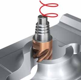
Figure 4.4 – Circular incision with a circular interpolation
Circular incision – in the implementation of the circular interpolation allows to achieve the minimum thickness chip output and minimize the cutting corners, reducing vibration and getting maximum performance.
The work of mills begins with actions on a form, after that it moves in a circular trajectory and begins to delve into the form, initiating the process. Get thin shaving when doing this a little easier, because you need only one additional round feeding over form – milling cutter will just start working a little higher and will move according to circular pattern delving into the surface of the form itself. Many do not perform this extra step and become witnesses of the same negative effect of vibration, reduced tool life and so on.
Mechanical milling with deep plunge
You have to get a decent experience in the field of positioning cutters over form, to achieve the desired accuracy. When the mechanical milling with deep plunge, a 70 percent plunge is optimal. This gives carbide plates time to shrink in proportion to the effort on the tool and thin shavings output allows you to gradually reduce this compression. Again, all this happens very quickly, but carbide inserts are not very good at a time remove the pressure of the large chip - sharp change of the load of compression to stretch becomes the reason of breaking off carbide output. While shallow incision, which is used mainly for contouring, cutting-25 % of the cutter diameter is optimum from the point of view of tool service life and performance.
It is important to bear in mind the possible consequences of the appearance of the large chips on the output from the provisions cutters over form. Most manufacturers centralt cutter above the center of the workpiece, and the output occurs thick shaving. Instead, the process should be optimized to provide the smallest chip thickness.
Associated and counter-milling
It is also important to distinguish milling supply (associated milling) and milling against filing (counter milling). Both methods are correlated with positioning cutters over form. When milling against the feed mill shifted to the right side, which again leads to the appearance of the large chips on the output. In the implementation of pass-through milling supply cutter shifted to the left side, and shavings the output is fine. This process is called milling supply, because the cutting effect is achieved due to the rotation of the milling machine in one direction with the presentation of the material. When milling against the feed mill is limited compressive forces[12, 13].
Continuous cutting mills
Continuous cutting mills is another method of output for optimized performance. It should be noted that the passage width (the width of the processed material) remains unchanged during the whole process. Most often in the manufacture of models, stamps and press-forms cutter moves around a form, giving the latter different features. This result should be achieved by moving cutters) to a specified radius, rather than a series of straight-line passes (see figure 4.5).

Figure 4.5 – Cutting by mechanical milling. (Animation: 16 frames, 0.5 sec. a delay, the size are 80 KB, unlimited number of repetitions, the program – Easy GIF Animator)
The cutter continuously interact with the workpiece. Many manufacturers use straight passages, but it's not a good situation, because such actions load and unload the spindle, a vibrating, reduce the service life of the tool and significantly reduce the overall performance of the machine. When the mechanical milling with circular flow is used to start processing of the component and the cutter moves over a defined radius when reaching the corner pieces, we can get thin shaving outlet, to maintain the level of cutting constant (even in the corners) and ensure sustainability.
Chipping and positioning cutters
Processing over the slots or openings will make the process unsafe, so repositioning cutters and modify the program to output was always thin shavings. Again, many manufacturers make the program work cutters passing directly above the cavities (see figure 4.6, top). This approach not only initiates vibration and instability, which was discussed earlier, but also carries out milling against feed and milling by applying for the same travel cutters, reinforcing unwanted effects. Instead, manufacturers must use the path to the right. It is necessary to conduct a circular incision, maintaining the continuity of the process – this will allow you to get thin shaving outlet (see figure 4.6, bottom).
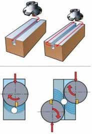
Figure 4.6 – Chipping and positioning cutters
Processing over the slots or holes that are present in the component, will make the process unsafe. Repositioning of milling machines and machining to rounding of these cavities will increase security and will allow to reach maximum efficiency.
Processing of molds, patterns, stamps: profiling
In the manufacture of models, stamps and press-forms is a significant amount of work on profiling making the generated component necessary features. All the same equipment mechanical milling with circular flow and continuous cutting by moving cutters) to a specified radius allow you to get thin shaving outlet, resulting in maximum performance (see figure 4.7).
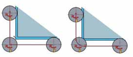
Figure 4.7 – The trajectory of cutting at contouring, external corners
Making the models, stamps and press-forms encompasses many internal corners, and no one will tell whether the cutter to vibrate when the achievement of one or another corner. To avoid problems, arc cutting when approaching the inner corner should be about 50 degrees. However, when the mill is included in the corner, this arc cutting is increased to 140 degrees because of the material appearing before the instrument in areas that have not yet been processed. Many manufacturers provide a 90-degree change of direction to start processing a different area of the form. This causes vibrations, because the arc cutting exceeds 90 degrees and the load on the mill reduced.
This means that a programmed change of direction actually causes the machine to freeze movement cutters, resulting pressure on the instrument is lost and starts vibration. Then cutter begins to move in the other direction, after which the pressure and stress on the instrument again increase. While increased efforts for the instruments and the load on the spindle mill will continue to vibrate while the load becomes high enough to stabilize the spindle. The most correct in this case would be the use of programmed radii to support continued plunge, to keep the effort on the spindle and the mill, and to avoid stopping the machine (see figure 4.8).
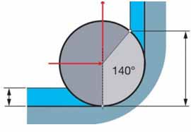
Figure 4.8 – The trajectory of cutting interior angles – end grinding
Corner treatment often initiates vibration; correct programming of passing angles will allow to increase service life of the tool and will lead to the inflow data for cutting calculation on a CNC machine.
5. Prospects and advantages of introduction of modern cutting tools and modern processing strategies
The right choice of cutting tool plays a key role in increasing productivity in the production of stamps. The emphasis is on import cutting tool with optimal geometry of the cutting part and with variety of types and configurations of the tool.
- Guaranteed stability of the import tool is 4 times higher than the cutting tool, made according to GOST standards.
- Improvement opportunities chip breaking, due to complex forms replaceable carbide inserts and opportunities in their replacement.
- The breadth of opportunities when the cart is studied directly in the cutting zone.
- The warranty on the tool from the manufacturer, when the implementation of the norms of use prescribed by the manufacturer.
- When all points, instrumental framework is flexible and can be tailored to the processing of other sizes of stamps, substantially reducing the time of preparation and processing of the products.
- At the same time, the import tool gives a better surface quality than domestic analogue, reducing the number of crossings for the treatment 1.5 times.
- The use of the tool with replaceable throwaway plates entails a reduction in the production of dies, due to low wear of the skeleton of the tools and capabilities recycling of recyclable materials in the form of hard-alloy plates.
- Optimization strategies processing will allow to significantly increase the performance and more than 1.5 times to reduce time of receipt of a unit of production.
- Feasible extraction of the metal in the form of bulk solids, instead of layer-by-layer removal in the form of chips.
Preliminary conclusions
In the given work the analysis used cutting tools, optimized and advanced processing strategies, and concluded:
In steps will be achieved the main goal – improving performance, reducing processing time and a significant reduction of production costs.
In case of successful implementation of this complex action – you will get a high-tech and highly organized production, cost-effective products, and for the customer and for the production, with all modern standards and requirements for products, including ecological.
When writing this abstract master's work is not done. Final completion: January 2014. The full text of work and materials on the topic can be obtained from the author or his head after that date.
The list of the used literature
- Кожевников Д. В., Гречишников В. А., Кирсанов С. В., Кокарев В. И., Схиртладзе А. Г. Под редакцией С. В. Кирсанова. Режущий инструмент: Учебник для вузов- 2-е изд. доп. – М.: Машиностроение, 2005. – 528 с: ил.
- Терновой Ю.Ф., Канюк В.И., Терехов В.Н. Справочник по инструментальным сталям. 2-е издание – Х.: «Металлика», 2009. – 242 с.
- Соловцов, Л.Г. Степанский, В.Н. Субич, В.А. Ульянов, З.Г. Унанян, А.Е. Феофанова, А.П. Шляхин, С.С. Яковлев. Ковка и штамповка: справочник. В 4 т.
- Режущий инструмент в производстве штампов и пресс-форм. Краткое справочное руководство. ISCAR IMC Group.
- Автоматизация проектно-конструкторских работ и технологической подготовки производства в машиностроении / Под ред. О.И. Семепкова. В 2-х т. Том 2. Минск. Вышейшая школа. 1977. 334 с.
- Акастелова Н.А., Вдовий С.И., Щупляк Г.И. Расчёт на ЭВМ раскроя листового материала при вырубке деталей из полосы // Кузнечно-штамповочное производство. 1983. № 4. С. 18—19.
- Арефин Ю.И., Швайнштейн И.С. Прогрессивная штамповочная оснастка. Л., Лениздат, 1982. 111 с.
- Динер И.Г., Брун В.Я., Бирин Б.В. Конструкции твердосплавных разделительных штампов. Рига, ЛатНИИНТИ, 1982. 24 с.
- Динер И.Г., Брун В.Я., Стеблюк В.И. Проектирование и изготовление твердосплавных штампов // Кузнечно-штамповочное производство. М., Машиностроение, 1979. № 8. С. 28—30.
- Дурандин М.М., Рымзин А.П., Шихов Н.А. Штампы для холодной штамповки мелких деталей. Альбом конструкций и схем. М., Машиностроение. 1978. 108 с.
- Системы автоматизированного проектирования: Типовые элементы, методы и процессы / Д.А. Аветисян, И.Л. Башмаков, В.И. Геминтерн и др. М., Изд-во стандартов. 1985. 180 с.
- Справочник по заготовлению и ремонту штампов и пресс-форм / В.С. Мендельсон, Л.И. Рудман, М.Г. Аскинази и др. Киев, Техника. 1979. 176 с.
- Стеблюк В.И., Марченко В.Л., Белов В.В. Технология листовой штамповки. Курсовое проектирование. Киев, Вища школа, 1983. 280 с.