
Abstract
Content
- 1.The problem and its relation to scientific and practical tasks
- 2. Analysis of research and publications
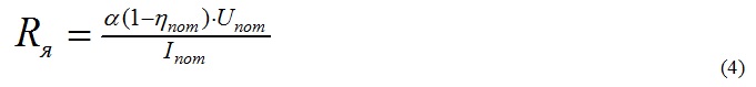
- 3. Problem
- 4. The material and results
- Conclusion
- References
1. The problem and its relation to scientific and practical tasks
Create shearers for thin layers with high functional and parametric performance is impossible without the use of the mechanism of movement of electric drives. In particular, in Ukraine are beginning to be widely used variable-speed drives. However, using a frequency-regulated drive, we are faced with the problem of securing the necessary control range of feed rate in the mechanisms of movement and load distribution between drives.
Shipping in Variable Frequency Drives two propulsion mechanisms moving shearer traction with hard wearing body dynamic nature due to, firstly, the unevenness of the resistance of the machine (power to the executive branch and the frictional forces in the bearings) and, secondly, the imperfection of engagement stars of rail. Accordingly, it may be roughly divided into two components load in the drive. The vibrations corresponding to the first component, there are occasions in both stars in phase. For other component is characterized by the presence of both phase and don't together oscillation period is equal to the length of one tooth meshing stars. The amplitudes of these oscillations depend on the phase shift between the start meshing teeth of drive rating with lantern rail, average velocity and the nominal slip motors. For the second component is also characterized by low-frequency vibrations, which is the period of time combine to move a distance equal to the length of the rail section .
For reasons that are as dynamic nature of the load , an important role in the selection of parameters occasion, the source data for the calculation of the strength and mode of playing a constant point, which is defined as the maximum value of midrange torque of the electric motor in which he at steady state load can work consistently with stall[1].
2. Analysis of research and publications
Studies have shown that on the basis of the drive motor DC provides a higher feed rate range adjustment mechanism for moving at the same power than the frequency - controlled drive. The literature has not found ways to increase the range of frequency- controlled drive mechanism moving two propulsion shearers [2].
3. Problem
In this paper we analyzed the possible range of adjustment in the engines of direct and alternating current, as well as on the basis of the clutches slip and braking. Similarly, the analysis of mass- dimensional parameters and load distribution between drives in various electric drives shearers.
4. The material and results
At present, the mechanism for moving shearer not solved the problem of controlling the speed range. As objects of comparison made adjustable frequency drive and motor drive based on direct current.
Table 1 – The characteristics of the drive moving with a pulling force of
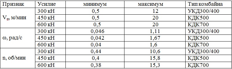
Define the range of adjustment actuators move shearers at the AC motor. The range is found from the moment the line of sustainable crossing the line since the required tractive effort given to the motor shaft.
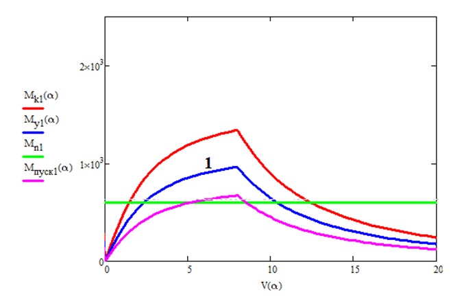
Figure 1 – Mechanical properties about filing based on variable-frequency motor 2x30 kW.
The minimum velocity of the shearer should not exceed 0.5 m/min. We see from curve (1), the minimum velocity of the harvester 2.5 m/min, maximum 10 m\min. Actual range received 4.
Steady point was determined from:

The critical point is calculated:
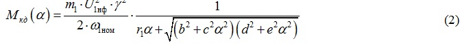
where Mk(a)= 2MCD(a) – a critical moment two propulsion drive;
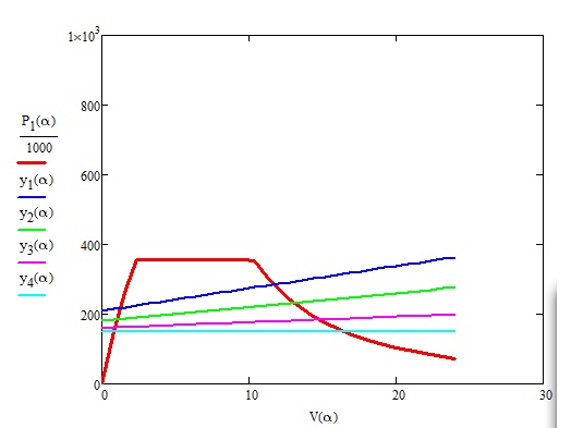
Figure 2 – depending on feed speed traction effort mode spans Yn, seizures Yn1, Yn2, Yn3 (resistance to cutting by 120, 240 and 360 N/mm) for 2x30 kW.
If necessary traction required 300 kN range does not match the actual, which means that the maximum tractive effort does not meet the maximum feed rate. For about 2?30 kW at the resilience of cutting 360 N / mm displacement speed of 12 m/min, but towing capacity of 280 kN.
We see that the actual range is not provided for maximum resilience cutting (360 kN/m).
The resulting range characterizes the work over in the most difficult circumstances, such as max. resistance to cutting max. angle of incidence of the reservoir. In reality, these values are much smaller and the adjustment range is significantly higher.
Consider the possibility of increasing the range of speed control for a given tractive effort through the use of AC motors high power 2x45 and 2x60 kW.
To extend the range of adjustment perform analysis at about 2x45 kW at 300 kN traction. To work on thin layers necessary to develop traction less than 300 kN. Minimum speed of movement on the necessary traction effort equal to 1.5 m/min and a maximum - 12 rev/min. The range of speed control is 8, which is significantly higher than the control range 2x30 kW but not enough to implement the necessary control range. For 2x60 kW minimum speed of moving about 300 kN 0.8 m/min, the maximum speed is 14 m/min, we have a range of 18, just not enough to implement the required range.
Mass and dimensions combine options regarding type UKD400.
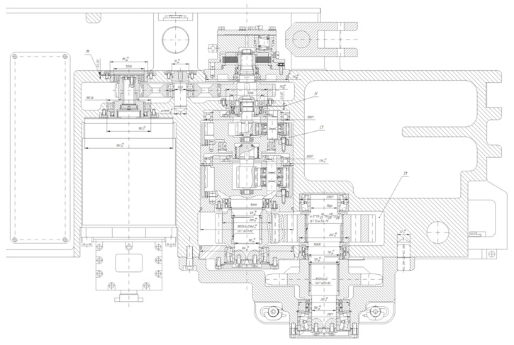
Figure 3 – actual size about filing shearer UKD400.
But as the band at this level does not provide the required thrust and the required speed, perform analysis capabilities over at the DC motor. The figure 4 shows that the range of adjustment in this regard is much higher when we need traction.
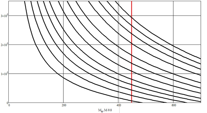
Figure 4 – The mechanical characteristics of the DC motor DRK27\19.6.
Mechanical constructed by:
The main parameters to determine the mechanical characteristics of the motor are:
For engine serial excitation a=0,75.
Consider the application of this subject as part of harvesting UKD300/400.
Consider the kinematic scheme over at the DC motor. For a given power 2x27 kW and nominal moment at 450 nm range is 50, gear reducer 120. Bear the entire range is not required, so calculate the gear reducer to the engine, which corresponds to a pulling force of 300 kN. To implement the thrust of 300 kN range is 24, while the minimum number of turns 125 r/min and maximum 2,950 rpm/min, gear reducer still 58. Combines Although such UKD300 and UKD400 can use small DC motors fashionableness (in master paper presents these calculations).
Consider this occasion consisting combine KDK500. If the traction of 450 kN and at nominal moment about it, we can get gear with gear ratio of 200, but the range is 50, this range is required. To implement the thrust of 450 kN range will be 40, with a minimum speed of 75 rev/min and maximum 2,950 rpm/min, gear reducer 96.
Consider this occasion consisting combine KDK700. Apply this drive with a capacity of 2x27 kW at 600 kN traction, we get the gearbox with gear ratio 280, but the entire range is required. To implement the thrust of 600 kN range will be 40, with a minimum speed of 75 rev/min and maximum 2,950 rpm/min, gear reducer 96. Planetary gear propose to keep intact, and the necessary adjustments to the overall transmission ratio by a pair z1i z2.
Thus, at the drive DC motor rated at 2x27 kW at almost the same dimensions develops the necessary traction and speed control range is the same as the drive based on AC 2x60 kW, with a control range of 50, higher than necessary (40) and drive 2?60 kW does not provide the required range at virtually the same size (109 dm3 and 94 dm3). To ensure 300 kN thrust required DC motor 14.6 kW. This engine provides the required range (24), with almost identical dimensions (83 dm3 and 78 dm3, respectively)[3].
Building Automated Electric from WA
An effective solution to the problem of development of alternative traction drive, flawed about DC is the use for this purpose without collector AC motor, as which can be used valve engine (ID ) in violation of the high-energy permanent magnets on the rotor, whose production is mastered leading electrical engineering companies.
WA have a number of structural and technical performance advantages with respect to existing types of electric cars: a lack of nodes that require maintenance-commutator less machine; provision of explosion; high overload capacity for the moment, enabling use in traction drive; high speed , the possibility of optimization of speed and loading; the highest energy performance; high reliability and increased service life of; low motor overheating when working modes of possible congestion.
Thus, the benefits of electronic ID management systems combine the best qualities of contactless motors and DC motors, and often surpass them.
Consider management principles and features of the electric through the use of WD.
Advances in the field of power and microprocessor technology have created favorable conditions for the development and production of a new generation of electric-based valve motors.
As you know, WA Brush semiconductor switch device is replaced, the anchor is on the stator and rotor is a permanent magnet [4]. Simplified diagram of a three-phase brushless motor with two-pole rotor is shown in Figure 5.
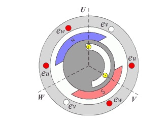
Figure 5 – Scheme of brushless
An important element is the engine position sensor rotor (DPR) which implements the feedback on the rotor position , performs the same function as the collector of DPT. His work can be based on different principles - photoelectric, inductive, the Hall effect, etc. It is best to use a motor with a photoelectric sensor, as it is almost instantaneous and gets rid of the delay in channel feedback of rotor position. Photoelectric sensor, which consists of three stationary sensor a, b, c, are closed alternately rotating shutter. Binary code obtained from DPR captures six different positions of the rotor. So DPR generates periodic signals, which control power switch occurs switch VT1 - VT6, connecting to the corresponding stator windings, so that each cycle (phase) of the engine includes two key and connected to the two series of three windings anchor. Armature winding U, V, W are located on the stator with a shift of 120 °. Temporary diagram of VD is shown in Figure 6. Where i and f - phase currents and the emf value; a, b, c - logic signals from the DWP; VT1 - VT6 - time slots of the relevant power switches.
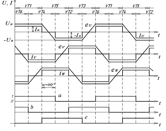
Figure 6 – Time diagram brushless
One cycle of the switch corresponds to one revolution of the rotor. The cycle is divided into six cycles ( interim phase ) , which corresponds to the spatial angle of 60 °. Switching is performed so that the flow of excitation of the rotor - F supported on a constant stream anchor. The interaction of the flow armature and excitation generated torque M, which aims to deploy the rotor so that the flow armature and excitation overlap, but when you turn the rotor under DWP is switched windings and armature flux returns to the next step.
We can say that if the DPT winding switched via the collector, the switching valve engines winding control system is carried out.
Brushless synchronous motor operates as a frequency proportional to the rotation of the rotor rotation frequency field. The main difference from the synchronous synchronization it is using DWP, resulting in this engine, however, the frequency of rotation of the field is proportional to the rotor speed and rotor speed depends on the supply voltage.
To control the characteristics of brushless most appropriate to use microprocessor control system ( ISU ).
Drive -based electromagnetic clutch slip (EMC)
Electromagnetic coupling consists of two mechanically unrelated pieces together - leading and famous. Driver unit, called an anchor and performed with a ferromagnetic material, is connected to the motor shaft. Powered portion, called an inductor, is located inside a top portion and is connected through a reducer or directly from the executive body of the working machine. At the inductor winding is located, which through slip rings connected to a power source. Excitation current IB can be adjusted, and thereby changes the frequency of rotation of the driven coupling, and hence the executive body. If winding inductor current flowed not breach , between him and anchor missing link and magnetic inductor fixed (w = 0).
The operating principle of electromagnetic coupling is largely similar to the principle of the induction motor, which has a massive solid rotor. By coupling mechanical characteristics w = f (M), which is the dependence of the frequency of rotation of the inductor (the driven part) w of developing them since Ms at different excitation currents, it is clear that, for example, at a constant point on hruzky regulation of excitation current to Iv1 Iv2 to change the rotational speed of the inductor to w11 w22.
Parametric electric speed control using electromagnetic clutch slip can't provide the required accuracy and large range of stiffness due to minor mechanical characteristics and decreases with decreasing excitation current handling capacity coupling. In order to expand the range of speed control and obtain high precision automatic control system is used.
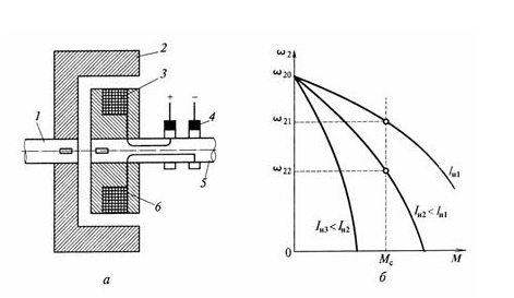
Figure 7 electromagnetic clutch: a – circuit device; b – mechanical characteristics.
Figure 7 shows a schematic diagram of the automatic speed control of electric drive from an electromagnetic clutch slip (EMC) of negative feedback on speed, carried out using tachometer BR, connected with the output shaft of the electric drive.
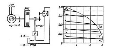
Figure 8 – Scheme of automatic speed control of induction motor using electromagnetic coupling and negative feedback speed [5].
Precision adjustment turns high, as well as the range of adjustment that can be up to (40 ... 50) and depends on the gain of the system; with the increase of the latter increases the allowable range of adjustment.
Losses in EMC consist of losses in the anchor (rotor) due to slip and allocated time; in the excitation winding in the rotor steel, determined angular speed and mechanical losses.
With increasing slip sliding losses predominate; rated power is spent on general-purpose excitement EMC nominal point from 75 to 1600 nm, an average of 3 to 0.7 % of the maximum power transmitted sleeve. In EMC special purpose for transferring large power points spent on excitation less.
The power factor of electric EMC depends on the transferred momentum and determined power factor of induction motor. If speed control is constant factor equal to the nominal , the power factor is maintained regardless of the nominal slip of EMC. When the fan load power factor depends on the EMS slip and falls dramatically with decreased speed.
The electric drive of the electromagnetic clutch slip attractive for its simplicity, high smoothness and low power regulating device for converting magnetization coupling. The use of electromagnetic coupling allows in some cases to simplify process automation and Cruise control execution of working machines.
Conclusions and directions of future research
Application Engine based on DC provide the necessary range when required tractive effort and at high speeds, with engine capacity of less than 2 times , as evidenced by the same German company Eickhoff SL300, SL500. However , that would provide the necessary pulling force necessary to change the gear ratio gearbox , which would entail a change in size. For low speeds and smooth adjustment using drive -based electromagnetic clutch slip or drag . It is also possible to use brushless drive to feed shearers , they have the same mechanical properties as DC motors.
In the master's work will make recommendations on the use of various electric drives in shearers to different customer requirements.
Список источников
- В.П.Кондрахин, В.В.Косарев, Н.И.Стадник, А.В. Мезников – устойчивый момент и диапазон частотного регулирования двухдвигательного привода механизма перемещения очистного комбайна.
- Кондрахин В.П., Косарев В.В., Стадник Н.И. – Электрические механизмы перемещения очистных комбайнов, 2010.
- Костенко М.П., Пиотровский Л.М. – Электрические машины том 2, 1972.
- Казачковський М.М. Комплектніелектроприводи: Навч. посібник - Дніпропетровськ.: НГУ, 2003, - 226с.
- Поздеев А. Д. – Электромагнитные муфты и тормоза с массивным якорем.
- Математическая модель для определения нагрузок в опорно-направляющих устройствах и механизме перемещения очистного комбайна УКД400/Кондрахин В.П., Лысенко Н.М., Косарев А.В. и др.//Научные труды ДонНТУ. Вып. 99. Донецк: ДонНТУ, 2005. С. 111-120.
- Решение научно-технических проблем при создании и внедрении современного горно-шахтного оборудования: сб. науч. тр. ГП "Донгипророуглемаш" под общей редакцией В.В. Косарева, Н.И. Стадника - Донецк: Астро, 2008. -800 с.