
Abstract
The content of the abstract
- Introduction
- 1. State of the problem, goal and tasks of work
- 1.1. Relevance of the topic
- 1.2. State of the question of the study of starting modes armored face conveyor
- 1.3. Goal and tasks of work
- 2. Development of a mathematical model of three drive armored face conveyor based on two-speed induction motors
- 3. Algorithm of running conveyor on the first speed in terms of equal loading onto the drive
- Conclusion
- References
- 1.3. Goal and tasks of work
Introduction
The most important in supporting of the effective work in coal-mining industry is coal conveying. The most popular kind of transport is armored conveyor.
Armored conveyor is machine for transporting of continuous operation. They are moving to pour materials occurs on fixedly mounted chute using scrapers, fastened to one or more traction chains.
Specialty of modern armored conveyor is using of cage induction motors [1].
Installing of such motors can exclude flywheel from the conveyor drive fluid , which has a number of operational deficiencies:
–significant loss of time for servicing;
–leak flow of motive fluid affects on the distribution of load between the drives;
–low reliability.
The field experience of two-speed armored face conveyers confirmed their high efficiency and, at the same time, revealed the problems associated with difficult starting loaded conveyors and insufficient reliability gearboxes and motors. [2].
These problems are related to insufficient knowledge of transient start. Investigation of starting modes three drive armored face conveyors is found out in this paper.
1. State of the problem, goal and tasks of work
1.1 Relevance of the topic
When starting a loaded conveyor sometimes critical situation arises, the so-called heavy launch pipeline
when the dynamic load on the drive components are significantly higher
than the static that manifests itself in a rapid induction motors overheating. High starting torque and high current are required to start overloaded conveyor particularly.
This causes a rapid drop in main voltage and instantaneous torque reduction.[3].
It is necessary to ensure coordinated operation of all drives for run the conveyor in such conditions. The rational choice of the algorithm run on the first drive of the conveyor (low) and the second (higher) rate it is one way to get this goal.
In practice when running two-speed three-drive conveyors the uncoordinated operation of actuators is obsevered. For example, in the picture 1 the oscillogram of the drive motors power of three drive conveyor KSD27 is shown at the start mining conditions [4]. As it is seen in the picture 1, when starting at the specified algorithm, both main motors are hardly loaded, and in some periods engines operate in generator mode.
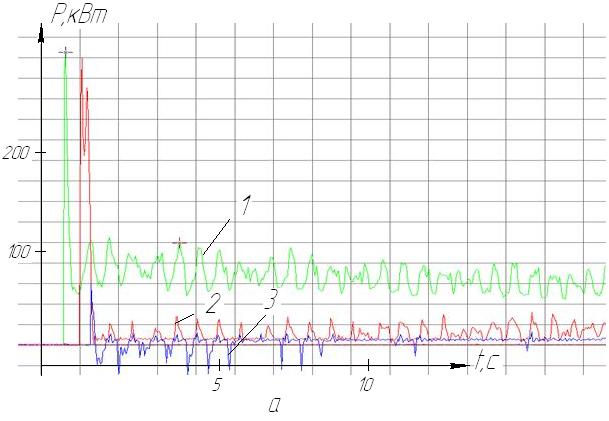
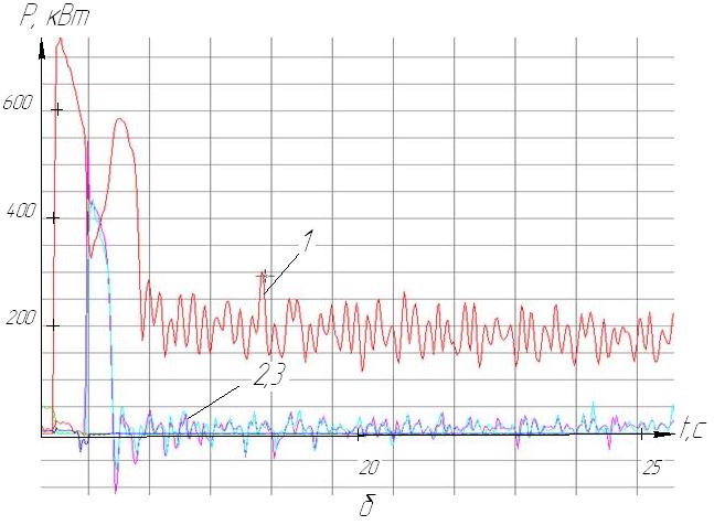
Picture 1. - oscillograms of three drive electric power P of the conveyor during starting on a low speed (a) and the transition to a high speed (b) (1 - tail drive 2, 3 - head actuators mine experiment)[4]
1.2. State of the question of the Study of starting modes armored conveyors
DSTU, Donetsk National Technical University, Moscow State Mining University, Kharkov machine-building plant Light Miner
, JSC Anzheromash
institute Dongiprouglemash
, JSC Donetskgormash
ON Donetskugleremont
, JSC Donbassugleremont
association Intransmash
and other organizations, research institutes, factories take part in researching and creation of armored conveyor.
Varchenko Y., Kashirskih V., Pereversev S., Braslavsky I., Eschin E., Kovacs K., Kopylov І., Ladenzon V., Masandilov L., Stockman І., Clerks V., Shkliarsky S., Shahmeyster L., Peisakhovich G. and other scientists were engaged into the launch of armored conveyor.
Ahrens K. [5], Brihta P. [6], Korneev S., Babenko N., Kondrakhin V., Stadnik N., Kosarev I., Kosarev V. were engaged into the launch of armored face conveyor with two speed engines.
Many researchers[1-16] devote рroblems of studying the transient and steady working conditions of armored conveyor. In these studies it is research as a complex nonlinear dynamical system, which has distributed in the space of elastic, inertial, dissipative and electromagnetic properties.
The main problem in armored conveyor is the imperfection of operation, namely, moving cargo and drawing body movement traction slip.
Since 1998 Institute Dongiprouglemash
began to create a series of armored conveyors system range KSD. It is made by JSC Donetskgormash
and also conveyors were developed for thin shallow and hollow - inclined strata KSD 26 and 26B, and conveyors KSD 210, KSD 29 for thick seams.
Аrmored face conveyor of a new technical level was observed in paper by Andreev G., Kosarev I. and others. Special aspects of the calculation and feasibility of application of these indicators pipelines in the industry were demonstrated [1].
Babenko M. considered questions about armored face conveyor in his paper [3]. Сoncept of the «Drive armored face conveyor» requires deep knowledge about specification materials-handling machinery. Many factors influence on running armored face conveyor. They are: charge and pipeline depth, coefficient of resistance of the chain in the upper and lower branches, dip angle and direction of transportation of rocks and other.
The reckoning of dynamics and traction drive body armored conveyor are present in the works of Skorodumova B. [7].
Korneev S. was investigation in his work [8] establish regularities of forming loads in the power system, the development of integrated research and scientific study ways and means of adaptation downhole armored conveyors to improve their efficiency by bringing the operational parameters of the conveyor in accordance real operating conditions. Two-speed conveyors starting modes in this work were not consider.
The article S. Korneev, J. Varchenko [9], were investigation armored conveyor as a complex nonlinear dynamical system, which has distributed in the space of resilient, inertial, dissipative and electromagnetic properties.
Davydov B., Skorodumova B. in their book Dynamics of mining machines
were investigation start armored conveyor as one drive conveyor system
with two lumped: reduced weight by the method of Rayleigh pulling unit and the driven load, and the reduced mass of the rotor motor and gearbox elements [10].
So the questions of rational justification launch mode two speed armored face conveyors are not well understood and require further research.
1.3. Goal and tasks of work
The goal of work is to improve operating efficiency of two-speed three-drive armored face conveyors at the cost of development of an optimal algorithm of their starting, which allows an even distribution of load between the drives, the minimal driving forces in the chain and the ability to run at high values of the resistance forces.
To achieve this goal it is necessary to make out the following objectives:
- develop and implement mathematical model in a software module of a two-speed drive three armored face conveyor type KSD;
- execute the identification of the model parameters, to carry out computational experiments by analyzing the results of computational experiments to establish patterns of influence on the starting load parameters of starting modes conveyor;
- get around the problem of optimal adaptation of run conveyor algorithm to predetermined operating conditions with allowance for pipeline depth, conveyor tilt, delivery in terms of providing a equal load on the drive head and tail;
- establish the optimal start mode of two-speed three armored drive face conveyors in terms of the formation of the pulling unit loads;
- define the rational algorithm of
heavy
run at elevated conveyor motion resistance forces traction.
2. Development of a mathematical model of three-drive armored face conveyor based on two-speed induction motors
A mathematical model which was developed by DonNTU is used for optimal adaptation of starting mode two-speed three-drive armored conveyors for work under specified conditions. It is allow to do research the formation of start-up loads in traction drives and drag out element [2,4].
Conveyor analytical model shown in picture 2 includes three-drive motors. Two of them are mounted on the head actuator ( turn on simultaneously) and one at the tail actuator.[11].
The following notations are shown on the diagram:
Jд – moment of inertia of the rotor of the 1st and 2nd electrical motors;
Mд1, Mд2 – electromagnetic moments of the 1st and 2nd electric motors;
Jзв – moment of inertia of the star drive;
Сп – stiffer modulus gear drive;
mг – mass weight, corresponding to one finite element;
Fc – drag force moving of mass m strand tail chain and freight (with allowance for weight component mgsinα when running on a formation dip angle α ).
As generalized coordinates for the mathematical description of the system adopted:
φд1, φд2, φд3 – degree of rotation rotor of the 1st, 2nd and 3rd motors;
φз1, φз2 – degree of rotation of the drive of the stars;
xpi, xxi – coordinate of the i- mass of the finite element – analogue tail chain on working and idle branches;
βп – coefficient of resistance gear drive.
From Picture 2 we can see the first finite element mass and working single branch is conditionally connected to respective drive stars, that is: xp1 = Rз⋅ φз1 и xх1 = -Rз⋅ φз2.
Picture 2 - Dynamic configuration of three drive armored face conveyor (animation, volume–108КБ)
As generalized coordinates for the mathematical description of the system, additional coordinate is adopted: φд3 – - angle rotor third motor.
3. Algorithm of running conveyor on the first speed in terms of equal loading onto the drive
Multidrive conveyors are provided certain simultaneous of switching on electrical motors of head and tail drive on the first and second speed. Two-speed launch of three drive armored conveyor to a low speed (NS) found out in this paper.
Time delay Δt1 it is one of the important factors determining the nature of dynamic processes at startup multidrive conveyor with two-speed induction motors, when starting on the NS main drive after advancing run tail.
Сhoosing the optimal parameter Δt1 is important because it may turn out that at work the engines are not helping each other but only interfere with.
When an untoward choice of the startup sequence to the first and second speed inconsistence of work drive is made it can lead to impossibility to start the conveyor.
Picture 3 shows as an example the process diagrams of optimal start algorithm of loaded conveyor KSD27 on the entire length, pipeline depth is 300 meters, which carries the rock mass upwards at an angle of 15 °. Mass per unit length on the canvas conveyor receives q = 90 kg / m.
Computing algorithm is launch of the tail drive, then through 0.42 with the simultaneous launch of two main engines. Equate Г11 – Г12 – (Δt1 = -0.42) - X1.
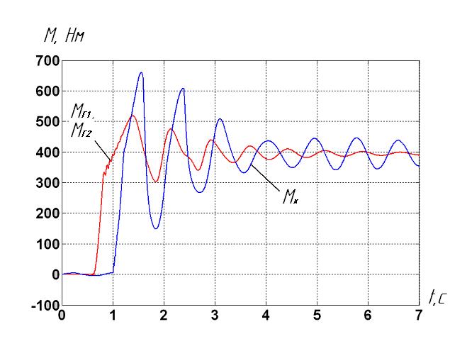
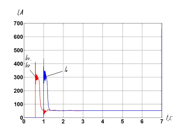
Picture 3 – Curve moments and growing floor of the drives at startup optimal algorithm: Г11 – Г12 – (Δt1 = -0.42) - X1 of three drive armored conveyor, pipeline depth is 300 meters
Picture 3 shows that the optimal algorithm is Δt1= Δt1опт = - 0.42 second. "-" Sign suggests that the first the main drive starts, and then the tail.
When conveyor starts at low speed with the found optimal value Δt1, load between the drives is evenly distributed [2].
A range of computational experiments for determination of the dependence of the optimal values of the parameters Δt1 transportation has been made. For different operating conditions necessary to estimate the optimal value of the delay time Δt1. if we use the results of the experiments. For example, in Fig. 4 we can see that for pipeline depth is 300 meters which transports the rock mass on level, the optimum value is 0.4 second, and during transportation at an angle downwards – 15° Δt1 = 0,2 second.
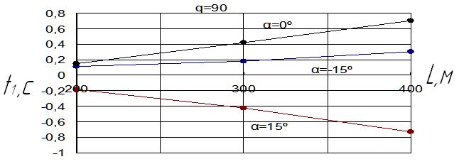
Picture 4 – Cross-plot of the dependence of the optimal delay time Δt1 on conveyor length L
It is worth noting that these results only apply to the present case, when the mass per unit length on the canvas conveyor receives q = 90 kg/m. Rational delay time Δt1 may differ materially from those shown in Picture 4 when it is a degree of loading conveyor.
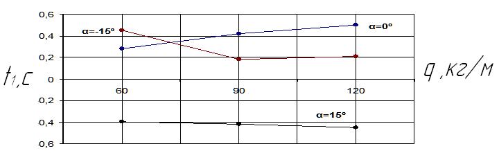
Picture 5 – Cross-plot of the dependence of the optimal delay time Δt1 on the mass of the load q
Picture 5 shows that for pipeline depth is 300 meters, which transports the mined rock on level at q = 120 kg / m, the optimum value Δt1 is 0.5, while transporting up an angle of 15° Δt1 = - 0, 45 second.
The obtained results allow to select the optimal value of the start delay of the main motor for operating conditions.
Conclusion
The optimal two-speed startup modes of the three-drive armored face conveyor to the first (lowest) and the transition to the second (higher) speed have been explained in terms of load balancing between drives , minimizing the maximum values of pulling unit tension and starting current , as well as the feasibility of "heavy" start.
The obtained results allow to determine the optimal value of the delay time Δt1 for each case, which varies depending on the operating conditions of the pipeline from -0.8 to 0.8 s ("-" Sign suggests that the first the main drive runs, and then - the tail)..
Further area of work:
- research and optimization of the algorithm parameters on the second run of the conveyor (high) speed;
- to provide evidence of the optimal two-speed run mode of three-drive armored conveyors in terms of the formation of the pulling unit loads;
- to define the rational algorithm of "heavy" run at elevated conveyor of motion resistance forces traction;
- to perform the modeling of blocking processes of working and single branch three-drive conveyor and assess the maximum values of occurring loads at the same time.
When this essay was writing master's work has not been completed yet. The final conclusion will be in December 2014.
References
- Андреев. Г.В., Косарев. И.В. Скребковые конвейеры нового технического уровня – Уголь Украины.- №9, 2003. – С. 30-34
- Кондрахин. В.П. Математическая модель для исследования нагрузок в двухскоростном многодвигательном приводе и тяговом органе скребкового забойного конвейера Кондрахин. В.П., Мельник. А.А., Косарев. В.В., Стадник. Н.И., Косарев. И.В. / Наукові праці Донецького національного технічного університету, вип. 16 (142), Серія: гірничо-електромеханічна, Донецьк, 2008, с. 132-140
- Бабенко. Н.П. Привод забойного скребкового конвейера // Уголь Украины, №5. - 2005.- С.28-29.
- Кондрахин. В.П., Стадник. Н.И. Пусковые режимы трехприводных двухскоростных забойных конвейеров . - Уголь Украины. - №5, 2011. - С. 45-48.
- Брихта. П. Технические возможности улучшения условий пуска загруженных конвейеров // Глюкауф.-№12, 1984.- С. 15-22
- Аренс. К. Условия запуска загруженных конвейеров с приводами обычного типа // Глюкауф.-№12, 1984.- С. 9-14
- РТМ 12.44.055-84 Конвейеры шахтные скребковые. Расчеты динамики привода и тягового органа. Гипроуглемаш, 1985
- Корнеев. С.В. Обоснование эксплуатационных параметров и способов адаптации скребковых конвейеров нового поколения. Автореферат дисс. … докт. техн. наук, – Днепропетровск, НГУ, 2007. – 35 с.
- Корнеева. С.В., Варченко. Ю.Э. «Пуск забойного скребкового конвейера в режиме монтажного натяжения тягового органа» Уголь Украины. –№7, 2004.
- Давыдов. Б.Л., Скородумов. Б.А. Динамика горных машин. М.: 1961.- 335 с.
- Обоснование конечно-елементной модели тягового органа скребкового конвейера // Кондрахин В.П., Борисенко В.Ф., Мельник А.А. и др.- Наукові праці Донецького національного технічного університету, вип.99, Серія: гірничо-електромеханічна, Донецьк, 2005, с.97-103
- Герман-Галкин. С.Г. Компьютерное моделирование полупроводниковых систем в MATLAB 6.0: Учебное пособие. – СПб.: КОРОНА принт, 2001. – 320 с.,
- Кондрахин. В.П. Оптимизация алгоритма пуска многоприводных двухскоростных забойных конвейеров / В. П. Кондрахин, Н.И. Стадник, В.В. Косарев, И.В. Косарев // Форум гірників-2009: матеріали міжнар. конф., 30 верес.-3 жовт.2009 р.- Дніпропетровськ: НГУ, 2009.- С.190-196.
- Скребковые конвейеры. Справочник / Под ред. А.В.. Леусенко. - М.: Недра, 1992. – 221с.
- Барышев. А.И., В.А.. Будишевский, Скляров. Н.А., Сулима. А.А., Ткачук. А.Н. Расчёты и проектирование транспортных средств непрерывного действия.- Донецк, 2005 – 684 с.
- Чугреев. Л.И. Динамика конвейеров с цепным тяговым органом.- М.: Недра, 1976.- 256с.