
Abstract
Content
- Introduction
- 1. Purpose and tasks of the research
- 2. Analytical Review
- 2.1 Diverter continuous hydraulic thrust (ONDG–93MR)
- 2.2 Orientator OGSH–3a
- 3. Designing trajectory directional wells that are drilled from mine workings
- 4. Designing multifunctional drilling complex
- Conclusion
- References
Introduction
One of the priority tasks of the Ukrainian coal industry is the safety and working conditions of miners to increase production capacity of coal mines. Make a difference in this direction allows efficient operation of mine degassing.
Current state of underground drilling in coal mines is characterized by the lack of solid technical and organizational approach to its implementation.
A significant number of wells that are drilled from underground intended for preliminary degassing, which depends on the scheme of development of coal seams and coal and is carried out by the host rocks. This led to the use of their time to drill exploration wells degassing machines and tools, not quite suitable for mining conditions, especially in full–hole drilling boreholes.
Modern foreign drilling equipment for decontamination is a highly productive, but his purchase and mass adoption greatly hampered by the high cost and the cost of maintenance and repair.
Way out of the situation at the moment may be the introduction of previously developed technical means and technologies that have not been previously implemented for reasons of economic and organizational nature.
At present DONNTU works on creation of modernized for modern requirements samples drilling tool based on existing constructive schemes.[3]
1. Purpose and tasks of the research
The aim of the research: develop a system design trajectory long degasification wells and drilling complex for drilling from underground mine workings
Research objectives:
- Analyze the current state of the art technology and directional drilling from underground mine workings
- Develop a methodology for automated design trajectory directional wells that are drilled from mine workings
- Investigate the influence of structural parameters of continuous standoff with hydromechanical system thrust to control the curvature of the well formed
- Develop a set of design documentation and drilling technology multifunctional drilling facilities
2. Analytical Review
2.1 Diverter continuous hydraulic thrust (ONDG–93MR)
For drilling upward boreholes in DPI in conjunction with themed cruises PO Ukruglegeologiya
designed hydraulically thrust diverter ONDG–93MR (Figure. 2.1). Dimensions ONDG calculated for the conditions of asymmetric slaughtering destruction.
Figure 2.1 – Diverter ONDG–93
Diverter consists of the camera body 12 with the slider 9 beyond the dimensions of the body under the influence of the expanding chamber 11 rubber covering shaft — tube 3. slider 9 is provided with a set of rollers 25 that the nomination of the slide contact with the wall, holding the deflector body from turning.
Upper Shaft — 3 pipe is used to connect to the orientator. Its pipe body provided with an opening communicating with an internal cavity rubber chamber.The lower end of the pipe 3 is attached a lock clutch 18, which are installed in the windows of cotters 24. Waterbars included in the annular groove of the plunger 18 and the orifice 17 in the housing groove. Under the action of the fluid pressure piston is axially movable down. The plunger moves the cotters, providing separation of shaft and housing whipstock. Through the rotation of the sleeve 18 is transmitted to the lower shaft 22, from it to the adapter 23 and the bit 33.
Diverter ONDG–93 operates as follows. Projectile coupled to the orientator is fed to the bottom of the hole and is set at a predetermined mounting angle. With the inclusion of the liquid feed stop clutch 18 is displaced from the slot, and outputs the housing 17 connected thereto cotters 24 located in the windows of the clutch 15. Shaft and the housing are disconnected.
Thus detached composite shaft 3, 15, 22 from the body, giving him the opportunity of independent rotation. Simultaneously, in the upper portion of the inner cavity of the shaft 3 is pressurized, leading to an expansion chamber 11 and the rubber advancement slider 9 up to the stop 25 in its roller borehole wall. Enclosures 1 and 2, resting on the opposite wall of the borehole carbide inserts on the eccentric projections provide a predetermined skew axis of the projectile.
2.2 Orientator OGSH–3a
Orientator OGSH–3a (Figure 2.2) consists of a housing 2, adapters 1 and 13, the cylinder 5 in which is located a piston rod 3 with sleeve 7 and 9. Stem 7 has an annular groove in which the ball 8 placed freely. Ball, rolling in an annular groove, always at the bottom. The sleeve 9 has a protrusion 14 whose width is less than the diameter of ball 8. Spring 10 in the rest position, displaces the piston rod 7 and 3 in the leftmost position. Flushing fluid from entering the inner cavity of the orientator protect the bellows 6 and 11. This cavity is filled with a lubricating fluid (e.g., glycerol).
Figure 2.2 – Hydraulic Orientator OGSH–3a
On the surface of the whipstock is connected to tracker so that at the location of the whipstock at a predetermined setting angle protrusion 14 of the sleeve 9 was a strictly below apsidal plane. At slaughter sequentially turn on and off the fluid supply, turning off, after each projectile at some small angle. The liquid flow moves the piston 3 and the stem 7 with ball 8 to the right, compressing the spring 10. Window 4 is opened, and the liquid passes freely through the gap between the housing 2 and the cylinder 5 in box 12 and further to the bottom. It occurs in all cases except for the position shown in the figure, when the projection 14 of the sleeve 9 at the bottom. The ball rests on the ledge, 4 window does not open, washing liquid does not pass through the tracker, and on the gauge has been a sharp rise in pressure, which serves as a signal about the desired position diverter.
3. Designing trajectory directional wells that are drilled from mine workings
The analysis of the possible schemes degassing shows that the technical problem described two possible drilling. In the first case the plane of curvature of the vertical degasification wells, its azimuth is constant and depends only on the angle of rotation about the axis of the drift wells at its sidetracking.
In the second case, the plane of curvature of the wellbore is inclined so that the straight portion of the well reservoir is parallel to the roadway at a predetermined distance therefrom. Designing and drilling under the scheme is more complex, but also provides high efficiency. [4]
Consider the situation related to the design of space–curved horizontal wells in reservoir occurrence degassed. In Figure 3.1 shows a diagram for the calculation of the basic parameters of the borehole.
Figure 3.1 – Scheme to the calculation of the plane of the spatial profile of the well
ДFor design purposes, the well profile is necessary to determine the coordinates of any point of N well, located on the mouth of lN length, angle ηN well at this point and turn it about the axis of the drift δN. Last determines the azimuthal direction of the borehole, because azimuth drift known.
Studies have provided a mathematical description of the borehole coordinates describing its spatial position relative to the excavation in the Cartesian coordinate system.
To automate the process of designing the well trajectory was composed calculation program, the system of the dialog box which is shown in Figure 3.2
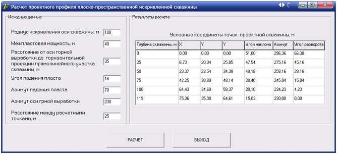
Figure 3.2 –System of the program calculate the geometric parameters of the projected wells
Specifying the initial parameters and the drilling can be calculated coordinates of points of the trajectory design, planning, and turning angles of the line of the roadway needed to guide and control diverter spatial position during drilling.
4. Designing multifunctional drilling complex
The drill is designed to guide and drilling degasification wells that rise flat and curved space–type. It includes orienting and diverting pulley (Figure 4.1). At the heart of the orienting unit used hydraulic system schematic orientator ball. Deflection system is an advanced complex standoff with hydro thrust designed based on the whipstock ONDG–93MR [5].
The spacer block is made from the camera body 12 with the slider 9 which fall outside the dimensions of the body under the action of the expanding rubber bladder 8 covering the shaft — the tube 13. Pipe body in an opening "a" communicating with the interior of a rubber chamber. slider 9 is provided with a set of rollers 10 which slide in contact with the nomination to a wall holding the rotation of the deflector body.
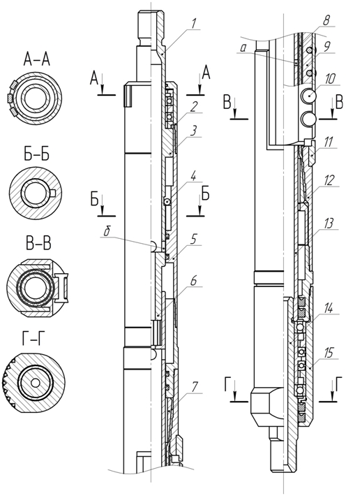
Figure 4.1 – The drilling assembly directional drilling
The outer surface of the body 2 and 15 reinforced with indexable inserts, perform the function of supporting elements and adjusts the intensity of the curvature of the well.
To the upper part diverter threaded nipple attached orienting 5. Inner part of the orienting pin is slotted portion for mating with whipstock shaft. In the lower part of the pin a slot adapted to accommodate a ball 4 at the orienting orienting the whipstock casing.
Through the housing 2 and orienting nipple 5 runs upper shaft 1. It is slotted locking assembly matched with the inner surface of the orienting pin. In the lower portion of the upper shaft 6 is placed slotted connector for compensating for misalignment of the shaft orientation. The shaft is provided with a hole "b" for the passage of washing liquid, which are designed for signaling the end of the orientation process.
In the annular cavity formed by the inner surface of the bore of the pin 5 and the shaft 1 at the upper portion of the splined shaft is situated orienting ball 4 rolls freely in the rest position under the action of gravity.
Developed drilling unit operates as follows. Before starting the drilling process is performed whipstock orientation to perform this shaft for pulling the drill string. The upper shaft 1 is capable of a small shift up the splined connector pin 5. This frees 4 ball that rolls on the annular cavity, occupying a position corresponding to the lower surface of the apsidal plane well. Lowered to the bottom shell, include the supply of drilling fluid and start cranking slow projectile body through the drill string. At the same time carry out periodic pulling and lowering of the upper shaft 1. At that moment, when the position of the slot aligns with the lower surface of the well apsidal plane, orienting ball 4 moves in the groove of the pin 5. Through this shaft 1 will move down the whipstock body, disconnect the splined shaft and housing, moves down the lower slotted connector, thus opening the side holes "b" of the shaft, and the washing liquid will be able to exit. Pressure in the supply line falls sharply, giving hydraulic signal the completion of orientation, which is celebrated on the gauge.
Due to the fact that the shaft 14 has a reduced flow cross–section, the fluid flow with increase in the inner cavity of the shaft 13 creates a higher pressure that leads to the expansion of the rubber bladder 8 and the advancement of the slider 9 up to the stop roller 10 at its borehole wall. Body 2 and 15, resting on the opposite wall of the well carbide inserts on the eccentric projections provide a predetermined skew axis of the projectile.
Figure 4.2 — Work drill directional drilling
Figure animated. volume — 55,5 kb.; number of frames — 12; delay time — 0,5с.; the number of repetitions — 7.
The advantage of a hydromechanical system thrust compared to the absence of a mechanical axial displacement element projectile body as an extension of the slide is only due to the pressure of the working fluid.
Conclusion
- 1. The hydraulic system orientation of the drill allows orientation of the projectile in the downstream, and horizontal boreholes.
- 2. Calculations show that projectile hydromechanically thrust deflecting elements can be used for drilling wells curvilinear ensuring a constant radius of curvature.
- 3. Work the projectile is independent of changes of axial load transmitted by the drill string and advancement of the slider thrust assembly occurs without moving the drill body elements.
- 4. To achieve the desired intensity of curvature should be used removable lining on the body and provide ongoing a whipstock drop in the cavity of the transfer chamber slide.
- This research project is in development and will be further improved.
- Structural scheme a whipstock continuous thrust with hydromechanical system provides reliable pressing intermediate support to the borehole wall, thereby increasing the stability of the dialed camber.
- Small radius of curvature is ensured by providing the difference in diameter bit and intermediate support removing support from the face and decrease the overall length of a whipstock.
- Increase the distance between the extreme points of supports housing a whipstock increases the radius of curvature of the well.
- To improve the efficiency of degassing of coal seams is advisable to use the extended space–deviated wells, including a curved portion that is drilled in rocks interstratal degassed before entering the reservoir, and a straight, directed toward the goaf is drilled parallel to the coal mining.
- Spatially curved profile type wells provides the richest set of azimuth at a high angle of inclination, and the success of its predetermined path depends on the accuracy of calculation of the coordinates profile and plan.
- Coordinates defining the spatial position of the point of the trunk depends on the angle to the horizontal plane of a well, the radius of the curved portion of the well, the distance between the developed and the degassing reservoir, dip angle.
References
- Юшков, А. С. Новые технические средства для искусственного искривления скважин при подземном бурении / А. С. Юшков, А. Д. Корсаков // Техн. и технол. геол.развед. работ в Сибири / Томск: Изд. ТПИ. – 1981. – С. 69 – 75.
- Горелкин А. А., Таран И. С. Технология направленного бурения горизонтальных скважин станком LHD–15A фирмы «Флетчер» /А. А. Горелкин, И. С. Таран. Краткая инструкция по эксплуатации станка LHD–15A – Донецк: Изд–во. Донбасс, 2008. – 34 с.
- Юшков, А. С. Проектирование криволинейных восстающих скважин сложного профиля: реф. карты / А. С. Юшков. – М.: ЦНИЭИуголь, 1979. – 18 с. — Вып.10 (118). — №835. — Деп. в ЦНИЭИуголь, № 1527.
- Разработка бурового инструмента и технологии направленного бурения скважин из подземных горных выработок: отчет по НИР (заключ.): Х–74–161 / ДПИ, рук. Юшков А. С.; исполн.: Бабичев Н. С., Грязнов В. Ф., Кабищер Г. Б., Корсаков А. Д., Удовиченко В. И., Филимоненко Н. Т. – Донецк, 1977. — 172 с.
- А. с. 744106 СССР, М. Кл2. Е 21 В 7/08. Снаряд для направленного бурения / А. С. Юшков, Б. Ф. Головченко, А. Д. Корсаков, О. П. Приходько, В. Г. Рожков, Т. Н. Филимоненко; Донец. политехн. ин–т и Тематическая экспедиция Производственного объединения «Укруглеология» (СССР). – № 2582171/22–03; заявл. 20.02.1978; опубл. 30.06.1980, Бюл. № 24.
- Нескоромных, В. В. Направленное бурение: учебное пособие / В. В. Некоромных, А. Г. Калинин. – М.: Изд. Центрметнефтегаз.– 2008. – 384 с.
- А. с. 595497 СССР, М. Кл2. Е 21 В 47/022. Гидравлический ориентатор / А. С. Юшков; Донец. политехн. ин–т (СССР). – № 2148082/22–03; заявл. 25.06.1975; опубл. 28.02.1978, Бюл. №