Abstract
О. Tolochko, D. Bazhutin Suppression of horizontal structural vibration of overhead crane in transversal direction given fixed trolley position This paper presents the velocity control system design for overhead crane gantry drives, which allows the suppression of elastic horizontal vibrations of its structure. A dual-channel velocity cascade control system with additional feedbacks of velocity differences between gantry wheels and trolley was designed to suppress the elastic structure vibrations. The acquired results of software simulation indicate that it is possible to achieve efficient vibrations cancellation of an overhead crane structure by means of electric drive.
Introduction
The main problem actively discussed in the literature concerning the cranes is the anti–swing control, that is, cancellation of payload swing motion. Many different approaches have been developed and verified in the past, some of the modern ones even consider the cable elasticity [1 – 5]. At the same time the crane structure is considered to be rigid, which means it cannot be deformed by any external or internal force. Yet recent tendencies of increasing the crane dimensions lead to increase of structural vibrations. In [6] it is shown, that for overhead cranes with long gantries the vibration magnitudes in gantry travel direction are of several centimeters value, which leads to an increase of mechanical stresses and reduces the lifespan of the crane due to the fatigue processes.
Investigating the elastic vibrations of crane constructions has become the state of the art in the control engineering during the last years. The main problem with it remains the way to establish an adequate and simple mathematical model, since the elastic deformations of mechanical structures with distributed parameters, like crane constructions, are described with partial differential equations, which are commonly solved via mesh or finite–element method, thus obtaining the deformation values at different points. The finite-element method is used for
Оanalysis of vertical elastic vibrations of a gantry crane including the payload swing dynamics in [7]. The analysis of structural vibrations of a ship-to-shore container crane in the direction of trolley motion was carried out in [8, 9]. [10] Presents the experimental study of gantry stage elastic vibrations, which is considered to be a special case of overhead crane, containing elastic couplings between linear drives and gantry itself. Nevertheless, the overhead cranes did not receive much attention in terms of the analysis of horizontal structural vibrations, despite being widely implemented in various branches of industry. This makes up the actuality of performed research, presented in this paper.
In [11] it is shown, that the natural frequencies of structural vibrations of an overhead crane lies within the range of 1,5…8 Hz, which allows to implement various measures to suppress them by means of electric drive, since they lie within the passband of typical drive systems.
Due to the complexity of plant mathematical model the control systems are typically designed for a simplified linear plant model, usually presented as a multi-mass system. Such approach can be implemented by replacing the distributed parameters, namely mass and stiffness, with the lumped ones. In [12] a linear mathematical model of an overhead crane with the trolley fixed in the middle of the gantry was developed. Considering the wheels masses and stiffness factors of both gantry halves being equal the overhead crane with trolley is converted into a two-mass system, with the wheels merged into one mass.
The deformation analysis of the loaded beam hinged at both ends is the basis for parameter estimation for such system. For this case both distributed and lumped parameter models have the same natural frequencies, if point load at the center of the beam is increased by 17/35≈0,5 of the beam mass.
The adequacy of the developed lumped parameter model was investigated in Comsol Multiphysics simulation software, which is based on finite–element method, by comparing the simulation results of both models. It was ascertained, that the vibrations amplitudes of lumped masses in a two–mass model would match the vibration amplitude of corresponding points on a finite–element model with the least deviation when the following conditions are satisfied:
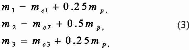
where mc1,3 – lumped masses of the first and second supports respectively, both of them containing the masses of wheels, electric drives and end girders; mp – distributed mass of gantry main girders; mcT – lumped trolley mass. The stiffness factor of the single elastic coupling present in this model can be computed knowing the lumped masses values and the frequency of elastic vibrations.
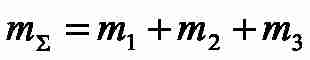
A case with the trolley fixed in any other position on the gantry, as shown in Fig.1, where the following notations are taken: v1, v2, v3 – linear velocities of the points, where the lumped masses m1, m2, m3 respectively are allocated; F1, F3 – linear forces equivalent to the drive motor torques; l – distance from end girder to the trolley; L – crane span, appears to be much more challenging. In this case the gantry with the trolley can be presented as a three-mass mechanical system, the kinematic scheme of which is shown in Fig. 2 with the corresponding block diagram presented in Fig. 3, where F12, F32 denote the elastic forces of lumped masses interaction. In order to simplify the obtained model so that it is linear the friction in lumped masses is neglected.
The mass distribution and stiffness factors to the left of the trolley с12 and to its right с32 can be treated as unknown functions of trolley position. Deriving these functions on the basis of beam vibrations analysis is complicated, but it can be estimated numerically for definite trolley positions and interpolated afterwards, as shown in [13]. In that article the analysis was carried out in Comsol Muliphysics simulation software in order to obtain both vibration amplitudes and frequencies.
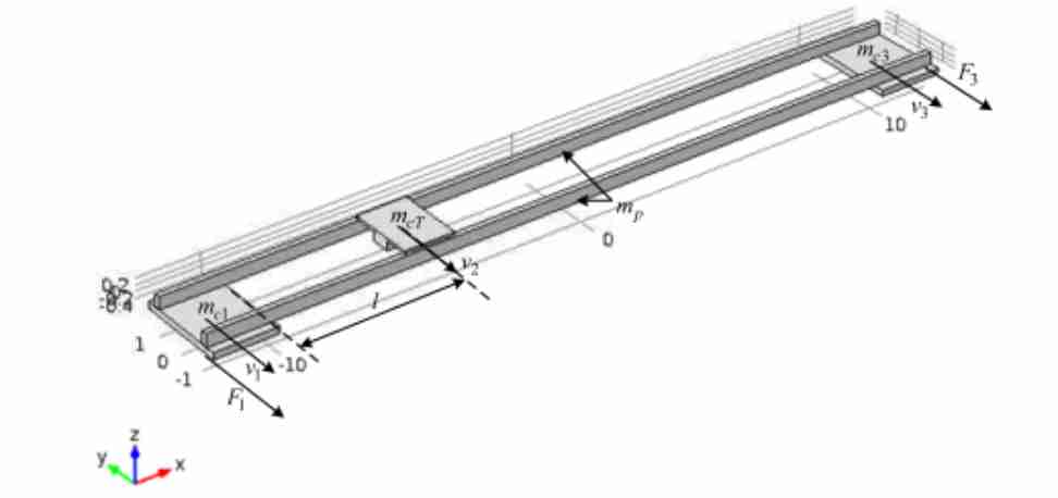
Figure 1 – Finite-element model in Comsol Multiphysics environment
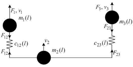
Figure 2 – Kinematic scheme of the tree–mass system
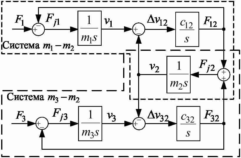
Figure 3 – Block diagram of the three-mass system
One of the most widespread vibration suppression techniques for such systems is the design of cascade control systems with additional feedbacks of elastic torque or velocity difference between lumped masses. The goal of the controller synthesis is to estimate the controller and feedback gains so that effective vibration suppression occurs. Yet the parametric synthesis of cascade control systems with mentioned structure for the three–mass plant, shown in Fig.3, has not been carried out before.
The aim of this paper is to design a coupled dual–channel wheel velocity control system, in order to suppress the horizontal elastic vibrations of overhead crane gantry in transversal direction without inducing a sufficient gantry crabbing, using a simplified linear model of its mechanical structure.
Plant analysis
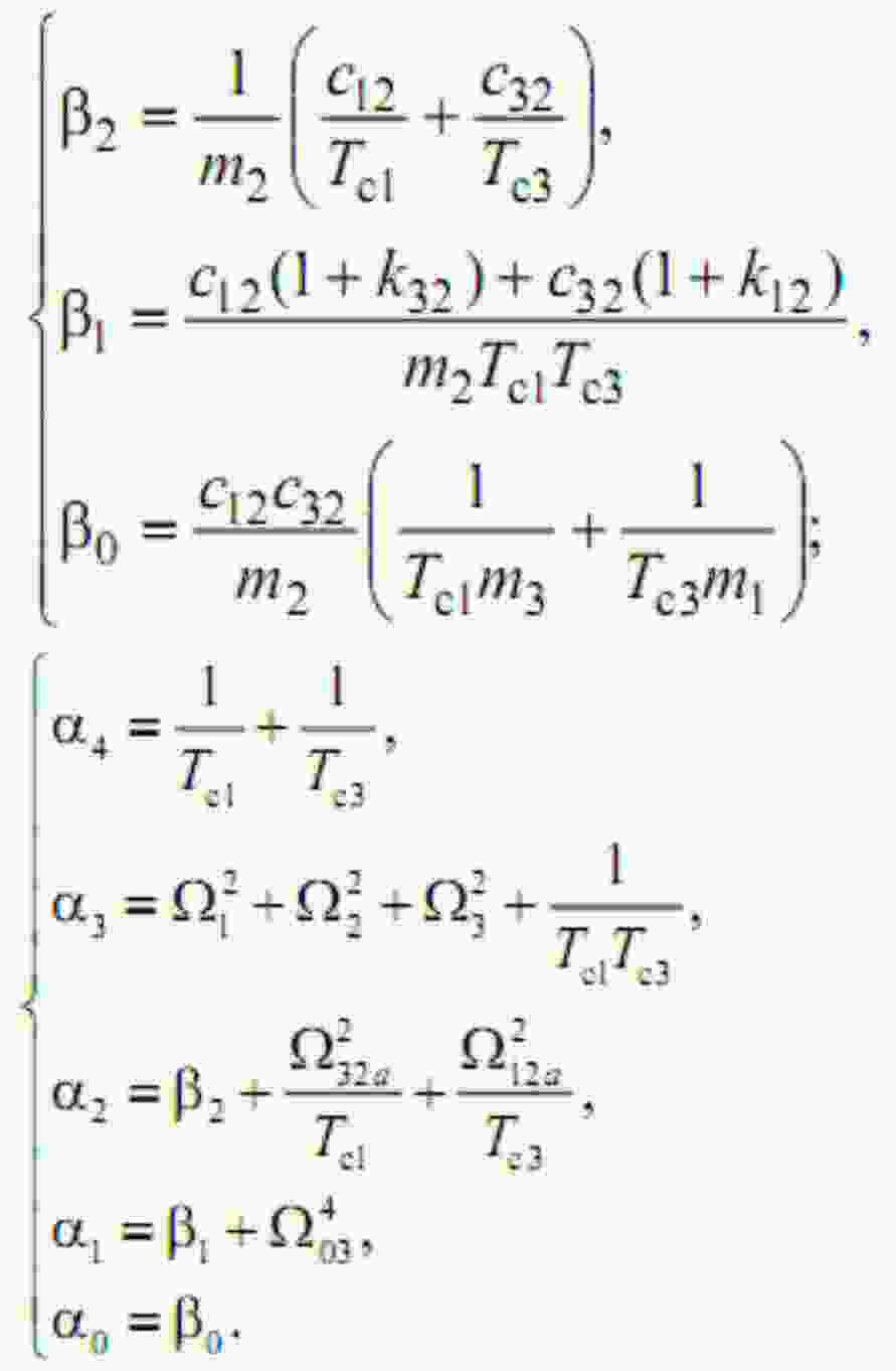
The first step of control system design would be the plant analysis. The characteristic polynomial corresponding to the model shown in Fig. 3 can be written as follows:

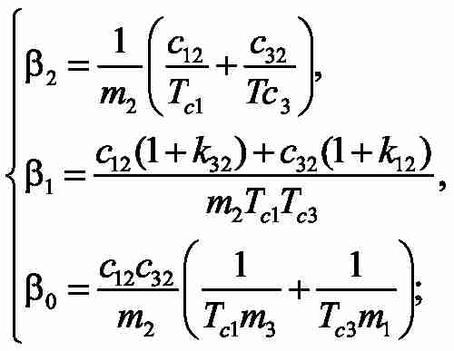
with
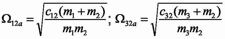
– natural frequencies of elastic vibrations in autonomous two–mass systems with lumped masses m1-m2 and m3-m2; as shown in Fig. 3;
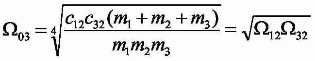
– geometric average root of characteristic polynomial of the three–mass system under study;
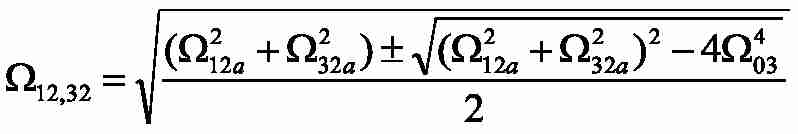
– natural frequencies of elastic vibrations in a three–mass system.
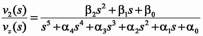
The transfer functions from the input forces to the dynamic force acting on the second lumped mass can be written as follows:
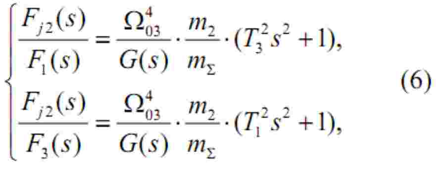
with
Analysis of the conventional dualchannel velocity cascade control system
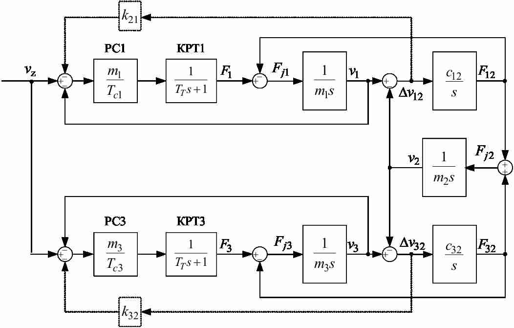
Figure 4 – Block diagram of velocity cascade control system for a three–mass plant
Using the approximate linear plant model a control system synthesis can be carried out in order to shape system responses with respect to desired performance.
In the simplest case the control of the gantry wheel drives is implemented in form of velocity cascade control system shown in Fig. 4 without additional feedbacks (dotted lines)
In Fig. 4 the motor current (force or torque) control loops MCL1 and MCL3 are presented in a simplified form as first order lag elements with small time constants TT. The simulation results for such system with the trolley allocated at the distance of l=8 m from the left end girder, where the lumped mass 1 m is assumed to be, with the overall crane span L=20 m are presented in Fig. 5. The velocity controllers VC1 and VC3 in this case were designed without taking into consideration the influence of elastic couplings between the masses, which makes the integration time constants of the velocity control loops Tc1=Tc3=2TT with TT=4 ms.
The time responses show slow damping of force and velocity vibrations, meaning unacceptable performance. One of the possible approaches to improve the system behavior is to reduce the velocity controller gain for both drives.
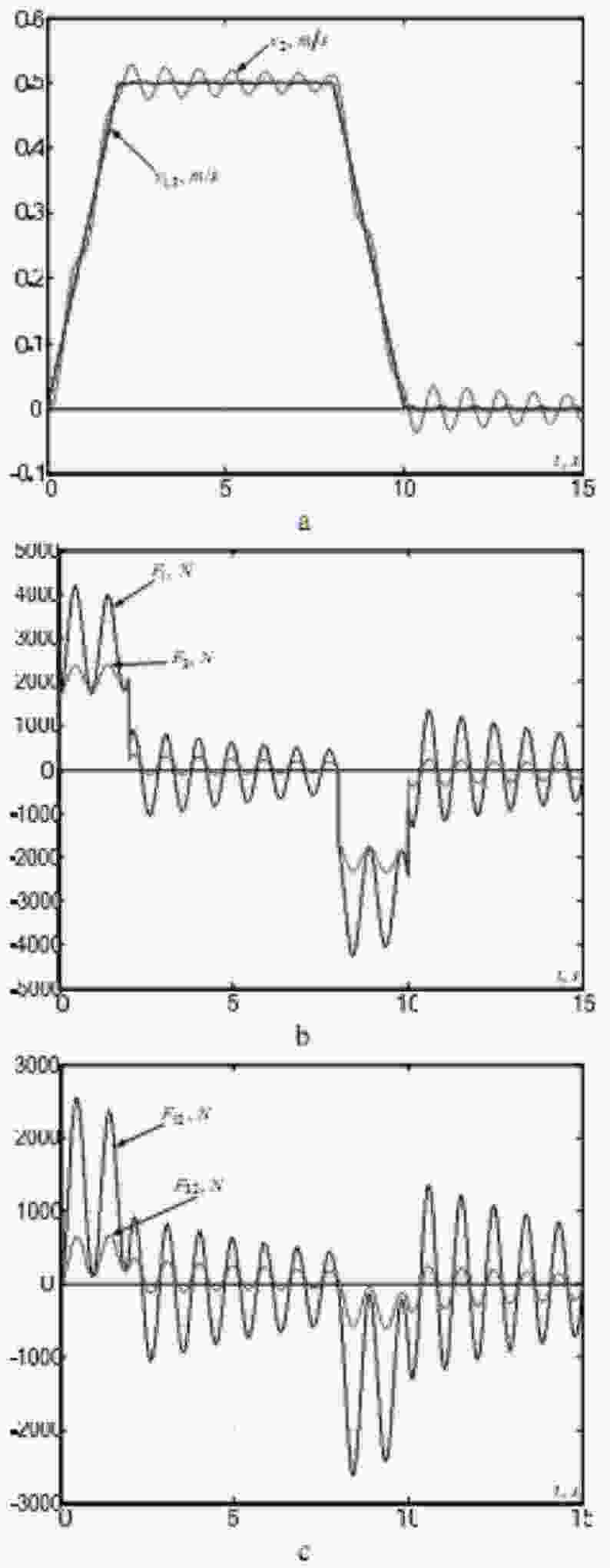
Figure 5 – Simulation results of a conventional velocity cascade control system designed withouttaking into onsideration the structure elasticity: (a) – velocities of lumped masses; (b) – driving forces; (c) – elastic forces
The new values of velocity controller time constants can be calculated to satisfy the magnitude optimum criterion. The technique described in [18] is used for parametric synthesis of the system shown in Fig. 4 assuming k12 = k32 = 0. A transfer function of the system from the reference velocity to the velocity of the second lumped mass is required in this case. As shown in [15, 18], considering very small response time of the current loop its lag can be neglected when deriving this transfer function (TT=0). It can then be written as follows:
with
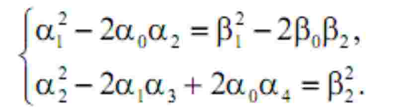
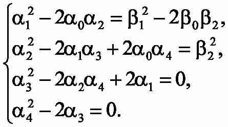
For the obtained transfer function we then compose the equations system that ensures the fulfillment of magnitude optimum conditions [19, 20].
In order to estimate the unknown time constants Tc1, Tc3 a system of two equations with two unknown parameters is to be solved:
Explicit solution of such system is very complicated and could be the topic of future researches. In our case, the numerical approaches were used, thus giving us the desired values of velocity controllers’ time constants, which resulted in the responses presented in Fig. 6.
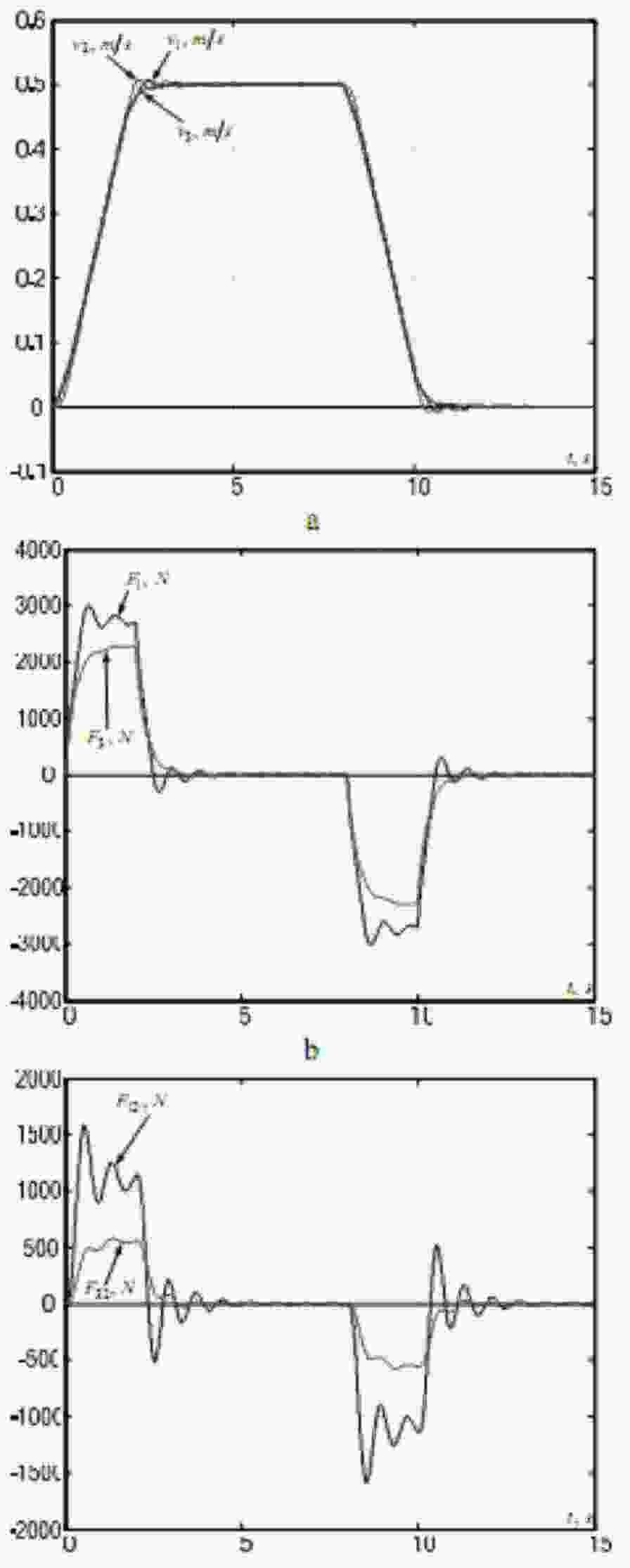
Figure 6 – Simulation results of a conventional velocity cascade control system designed with taking into consideration the structure elasticity for magnitude optimum criterion: (а) – velocities of lumped masses; (b) – driving forces; (c) – elastic forces
The simulation results show that, as in the case of two-mass systems, without the additional feedbacks of velocity differences the amplitudes and settling time of elastic vibrations cannot be reduced sufficiently. Therefore a velocity cascade control system with additional feedbacks should be investigated.
Design and analysis of a dual–channel velocity cascade control system with additional feedbacks of velocity differences between the lumped masses
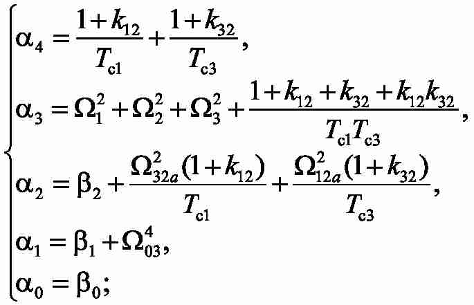
We use the same approach as previously, thus assuring the magnitude optimum criterion to be fulfilled for our system. The transfer function (11) will have following expressions for the numerator and denominator coefficients:
The synthesis is performed in much the same way as previously, but there will be four unknown parameters to determine ( Tc1, Tc3, k12, k32) and therefore a system of four equations is composed and solved numerically due to its complexity:
The simulation results of the designed velocity cascade control system with l=8 m are shown in Fig. 7. They confirm the efficiency of the proposed approach in terms of vibrations suppression at discussed points.
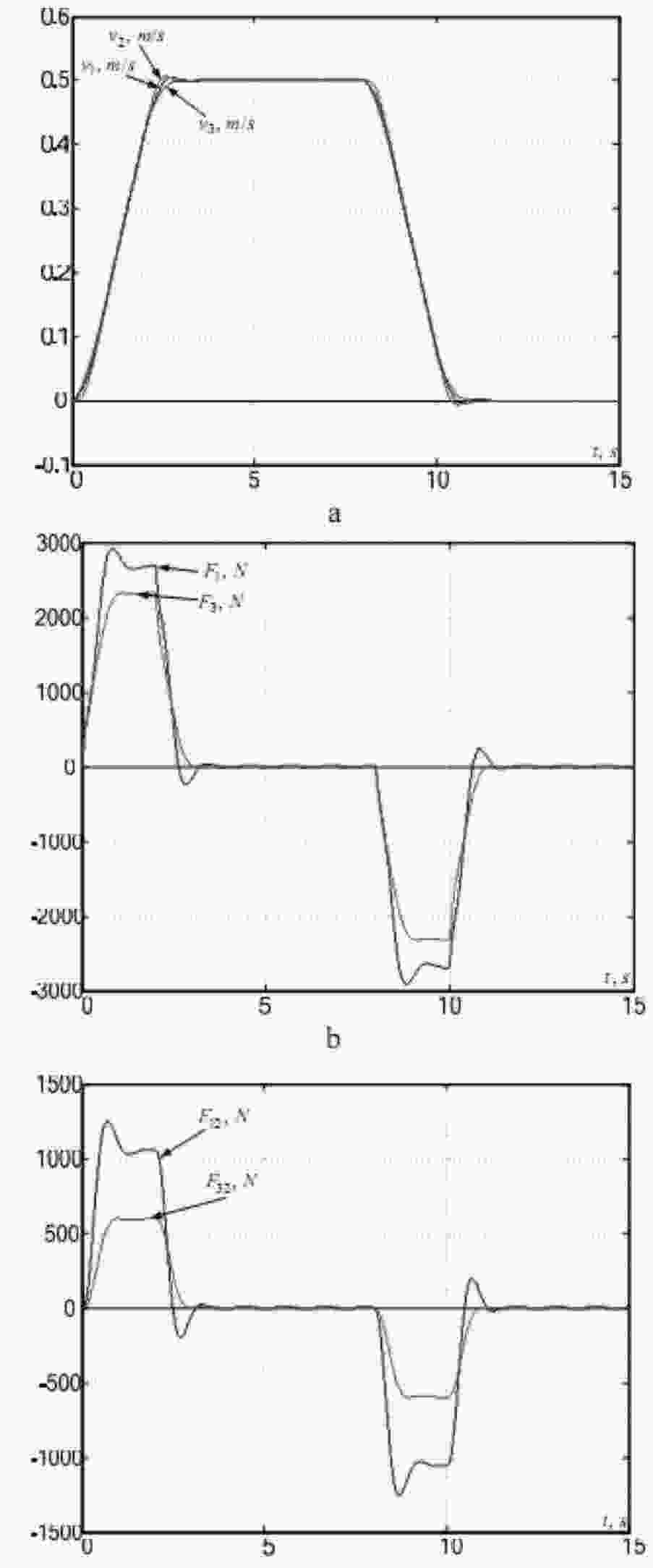
Figure 7 – Simulation results of a cascade control system designed in terms of magnitude optimum with additional feedbacks: (a) – velocities of lumped masses; (b) – driving forces; (c) – elastic forces
A set of simulations has been performed in Comsol Multiphysics simulation environment under the effect of force time diagrams shown in Fig.7, b, which confirmed the viability of the proposed technique of vibrations suppression for an overhead crane structure.
Conclusions
1. Designing a velocity cascade control system without additional feedbacks does cannot result in effective vibrations suppression.
2. Reducing the velocity controllers’ gains lead to insufficient improvement of vibration suppression efficiency
3. Velocity cascade control system with additional feedbacks of velocity differences is able to effectively suppress elastic vibrations albeit with increased overshoot in total elastic force and velocities time responses. The main advantage of such system would be its simple implementation since all fed back signal are directly measurable.
4. Proposed control systems with constant parameters can be used for vibrations suppression only at given fixed trolley position. An adaptive automatic control system can be considered and designed being able to suppress the induced elastic vibrations with the trolley moving along the crane gantry.
References
1. Ilharfi A. Control Design of an Overhead crane System from the Perspective of Stabilizing Undesired Oscillations, (2011), IMA Journal of
Mathematical Control and Information Publ., 28, – рр. 267 – 278.
2. Moustafa K.A.F., Gad E.H., El–Monerr A.M.A., and Ismail M.I.S. Modeling and Control
of Overhead Cranes with Flexible Variable-length Cable by Finite-element Method, (2005), Transactions of the Institute of Measurement and Control, 27, 1, pp. 1 – 20.
3. Singhose W., Porter L., Kenison M., and Kriikku E. Effects of Hoisting on the Input Shaping Control of Gantry Cranes, (2000), Control Engineering Practice Publ., 8, pp. 1159 – 1165.
4. Buch A., Palis F., Schwarzkopf A., and Albrecht K. Regelung Schwingungsfahiger Systeme hoherer Ordnung, (1997), Proc. Moderne Methoden der Regelungs- und Steuerungsentwurfs, Magdeburg, Germany, pp. 123 – 129. 5. Yazid E., Parman S., and Fuad K. Open-loop Responses of Flexible Gantry Crane System, (2011), Journal of Applied Sciences Publ., 11 (10), pp. 1716 – 1724.
5. Palis F., and Lehnert M. Motion Control of
of Crane Drives by Fuzzy-controller, (1992), Proc. ED&PE 1992, International Conference on
Power Electronics and Electrical Drives, Vol. 2, CSFR, 14–16 September 1992, pp. 297 – 301.
6. Prins G. Dynamisches Verhalten groBer Verladebrucken, (1979), Fordern und Heben 29
(1979), Teil 1, No. 11, pp. 996 – 1001, Teil 2, No. 12, pp. 1111 – 1113.
7. Yazid E., Parman S., and Fuad K. Openloop Responses of Flexible Gantry Crane System,
(2011), Journal of Applied Sciences Publ., 11 (10), pp. 1716 – 1724.
8. Pietryga U. Aktuelle Trends in der Entwicklung von Ship–to–Shore (STS) Container–crane, (2011), 19 Internationale Kranfachtagung, Magdeburg, Germany, pp. 128 – 140.
9. Recktenwald A. Aktiver Schwingungs –dampfer fur Krane, (2011), 19 Internationale Kranfachtagung, Magdeburg, Germany, pp. 142 – 146.
10. Garcia-Herreros I., Kestelyn X., Gomand J., Coleman R., and Barre P.-J. Model Based Decoupling Control Method for Dual Drive Gantry Stages: A Case Study with Experimental Valida tions, (2013), Control Engineering Practice Publ., 21, pp. 298 – 307.
11. Hannover H. –O. Schwingungen an Krananlagen und deren Auswirkung auf Funktionsund Bedienungskomfort, (1978), Integration von Maschinen – und Stahlbau, Fachtagung TU Karlsruhe, pp. 162 – 185.
12. Толочко О. И. Гашение горизонтальных упругих колебаний конструкции мостового крана / О. И. Толочко, Ф. Палис, Д. В. Бажутин // Електромеханічні і енергозберігаючі системи. Тематичний випуск Проблеми автоматизованого електропривода. Теорія і практика
– Кременчук : КрНУ, 2012. – Вип. 3/2012 (19). – С. 336 – 339.
13. Палис Ф. Анализ поперечных колебаний мостового крана при изменении положения тележки / Ф. Палис, О. И. Толочко, Д. В. Бажутин // Вісник Національного технічного університету Харківський політехнічний інститут
. – Харків : НТУ ХПІ
, № 36 (1009), 2013. – С. 36 – 39.
14. Бургин Б. Ш. Анализ и синтез двухмассовых электромеханических систем / Б. Ш.
Бургин. – Новосибирск : Новосибирский электротехнический ин-т, 1992. – 199 с.
15. Борцов Ю. А. Автоматизированный электропривод с упругими связями / Ю. А. Борцов, Г. Г. Соколовский – СПб. : Энергоатомиздат, 1992. – 288 с.
16. Герасимяк Р. П. Синтез электромеханической системы подъемных механизмов с
подавлением упругих колебаний / Р. П. Герасимяк, А. М. Ант, А. М. Рамарувахуака // Електромашинобудування та електрообладнання. – К. : – 1996. – № 48.
17. Schroder D. Elektrische Antriebe – Rege-lung von Antriebssystemen. 3. Auflage – Springer
Verlag. – 2009. – 1336 p.
18. Коцегуб П. Х. Оптимизация двухмассовых систем регулирования скорости / П. Х.
Коцегуб, В. А. Баринберг, О. И. Толочко, Р. В. Федоряк // Известия вузов. Электромеханика.
– 1998. – №4. – С. 54 – 57.
19. Kessler C. Uber die Vorausberechnung Optimal Abgestimmer Regelkreise // Regelungs-
technik. – 1955. – № 1. – Рp. 16 – 22. – № 2. – Рp. 40 – 49.
20. Коцегуб П. Х. Оптимизация систем управления по модулю амплитудно–частотной характеристики / П. Х. Коцегуб, О. И. Толочко // Изв. вузов. Электромеханика. – 1977. – № 6. – С. 679 – 684.