
Abstract
Contents
- Introduction
- 1. Theme urgency
- 2. Goal and tasks of the research
- 3. The study of thermal conditions in the TFC-AD
- Conclusion
- References
Introduction
The use of AC motors (asynchronous and synchronous), systems controlled electric industrial, opens up opportunities for a significant increase in performance as a result of tools and technologies to improve production, reduce costs and improve product quality.
These machines are characterized by a large power range (from a few watts to thousands of kilowatts), highly diverse in design, applied the cooling medium, cooling systems, and so on. D.
Inadequate study of thermal processes in the absence of reliable elektrodvi¬gatelyah and engineering methods for calculating heating of new designs predetermined consideration in this work primarily modeling of thermal processes such machines.
In this paper the question of heating motor with blown cover, as the most common and characteristic type enclosed induction motors. [6].
The most effective, and in most cases, virtually the only possible way to control the speed of the AC motor is the frequency regulation. Electric machines with adjustable frequency converters due to a number of their inherent disadvantages (high installed power equipment, low efficiency, inertia, etc..) Are not widespread.
A much more promising is the converter frequency that the rational design are free of flaws electric machine.
The development of semiconductor power converters for AC motors with adjustable output voltage and frequency are in two areas:
-ventilnye converters with DC link current and independent inverter;
- the converter without a DC link with direct connection for power supply and the load circuit.
In the first type of converters in the power of their industrial AC rectifier elements are necessary and standalone inverter. Control functions of frequency inverter output voltage carries and stress - the rectifier. Sometimes the two functions are performed by the inverter and the rectifier is performed unmanageable. A large number of schemes of frequency converters with DC link.
In the second type of power converters is made directly from the AC mains without an intermediate rectification.[5].
When using a direct converter is easy with the help of a control system to get the output current in the form close to the sine wave, which can be particularly useful when working on the engine medium and high power. However, frequency converters without a DC link and are inherent in some of the shortcomings. In particular, they consume significant network of reactive power. A typical disadvantage arising from the very principle of the inverter is limiting the upper limit of the operating frequency it is half the frequency of the supply voltage.
Since the majority of the industry engines produced at the frequency of 50 Hz, in this paper was selected for research autonomous voltage inverter with PWM and asynchronous motor with squirrel-cage rotor.
Since the output voltage of the stand-alone inverter is not pure sinusoidal shape, and in the investigation and the stator and rotor currents are pulsating in nature, you should check if the engine does not overheat in such conditions.[1].
1. Theme urgency
At this time, the thermal processes in electric motors are not well understood, and there are no reliable calculation of heat engineering metodoy new designs based on this in this paper mainly made of modeling thermal processes such machines.[3].
2. Goal and tasks of the research
The main objective of this work is the study of the thermal state of the induction motor powered by the autonomous voltage inverter with pulse width modulation. The load on the motor shaft is constant and correspond to nominal frequency and voltage of the inverter will change according to the law:

The interest of the thermal state of the motor drive system, blood pressure is because the output voltage of the inverter is not sinusoidal and pulse shape and therefore the currents of the stator and rotor have a sinusoidal but pulsating form. Ie in the harmonic composition of the harmonic currents present are different from the primary. According to the theory this is especially evident at low frequencies the output voltage. Therefore, in the form of investigating current and voltage at the output voltage frequency f = 50, 25 and 10 Hz.
3. The study of thermal conditions in the TFC-AD
In the simulation of TFC-BP were obtained curves of stator currents, the rotor of the engine at rated load torque, as well as the curve of the output voltage of the inverter.[2].
It is proved that in the heat of the engine the greatest influence odd harmonics. For the analysis will take into account the fundamental component and 3, 5 and 7 harmonic output signal currents and voltages. To isolate these components of the harmonic structure model is developed.[3].
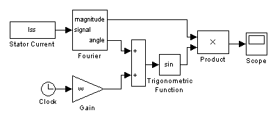
Figure 3.1 - The model for the isolation of harmonic components
The basic unit of this model is a block Fourier package SIMULINK, having the following parameters:
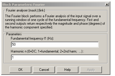
Figure 3.2 - Block Parameters Fourier
In the Fundamental frequency f1 (Hz) indicates the frequency of the input block, and in the Harmonic n (0 = DC; 1 = fundamental; ... 2) indicate the number of harmonics you want to highlight. On the oscilloscope observe the curve corresponding to said harmonic.
To account for these components in the motor thermal model input falls more than a sinusoidal signal and the sum signal corresponding to the selected harmonics.
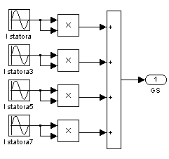
Figure 3.3 - Block account the harmonic content of the stator current
Each unit is combined with the names in Subsystem GS, GSU, GR - respectively, the sum of harmonic signals of current, voltage stator and rotor current. Thus a model for the study of the thermal state of the engine, taking into account pulsating inputs has the form:
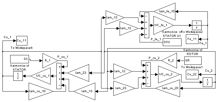
Figure 3.4 - Thermal motor model based on the harmonic content
The first experiment was carried out in the simulation system-AD TFC output voltage with a frequency f = 50 Hz.
After the analysis of the earlier schedules of the stator current and the rotor and the output voltage of the inverter by means of model selection harmonic components reduce the data in table 3.1
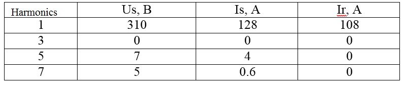
Table 3.1 - Harmonic structure of current and voltage at fc = 50 Hz, fr = 0.8547 Hz.
As you can see the third harmonic is absent in all current and voltage curves and the fundamental harmonic corresponds to the nominal parameters obtained at the motor supply voltage sinusoidal network.[4].
According to the results we obtain simulation graphics overheating including ripple currents and voltages.
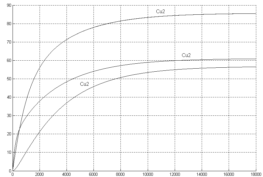
Figure 3.5 - overheating of the rotor θCu2 , winding θCu1 and Fe θFe1stator powered by a TFC with a frequency f = 50 Hz
tabulate the average temperature obtained by applying to the thermal model with sinusoidal currents and voltages of industrial frequency f = 50 Hz and the last curves obtained in the TFC-BP.
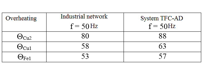
Table 3.2 – Overheating in food from an industrial network and system TFC-AD
By comparing the simulation results can be seen that overheating in the TFC-BP at f = 50 Hz above the rotor 8 °C, the stator winding 5 °C and iron stator 4 °C. From these graphs can be seen that the overheating of parts in the engine at the rated load torque and nominal frequency of the supply voltage, practically unchanged with respect to the mode of engine power in the TFC-BP at f = 50 Hz.[7].
Thus, the use of the developed model of the frequency converter to power the motors in industrial installations of various kinds does not change the overheating engine parts, that is, will not cause a violation of its normal thermal mode at rated speed.
Next, examine the thermal state of the motor at low voltage inverter frequency f = 25 Hz.
In the process of modeling the system TFC-BP waveform we get the following:
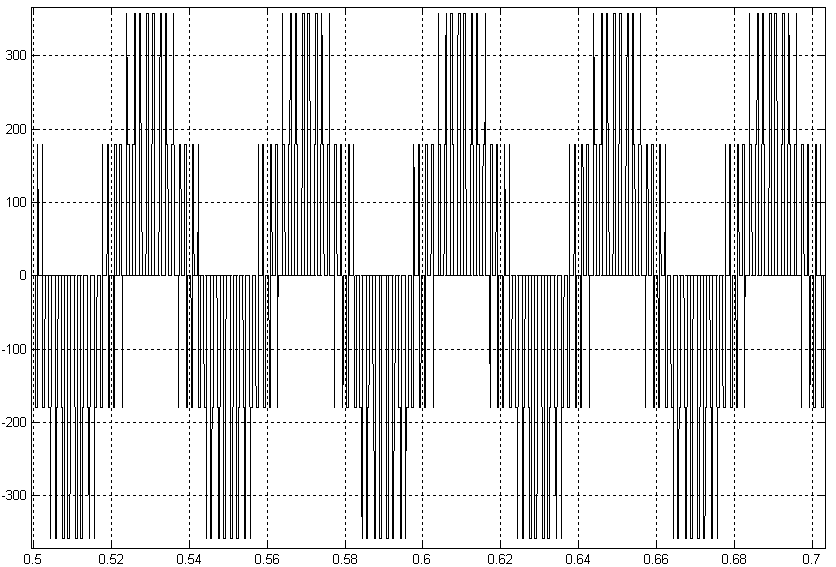
Figure 3.6 - The output voltage of the inverter at fz = 25Hz
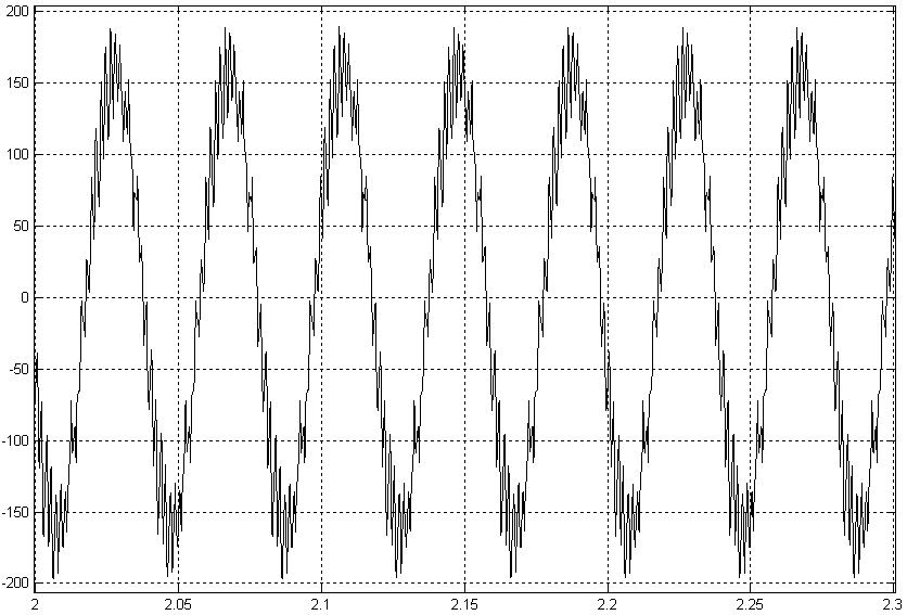
Figure 3.7 - Detail of the stator current Mc=Mном
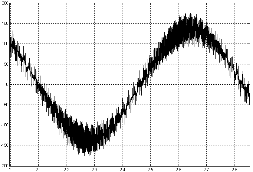
Figure 3.8 - Detail current rotor Mc=Mном
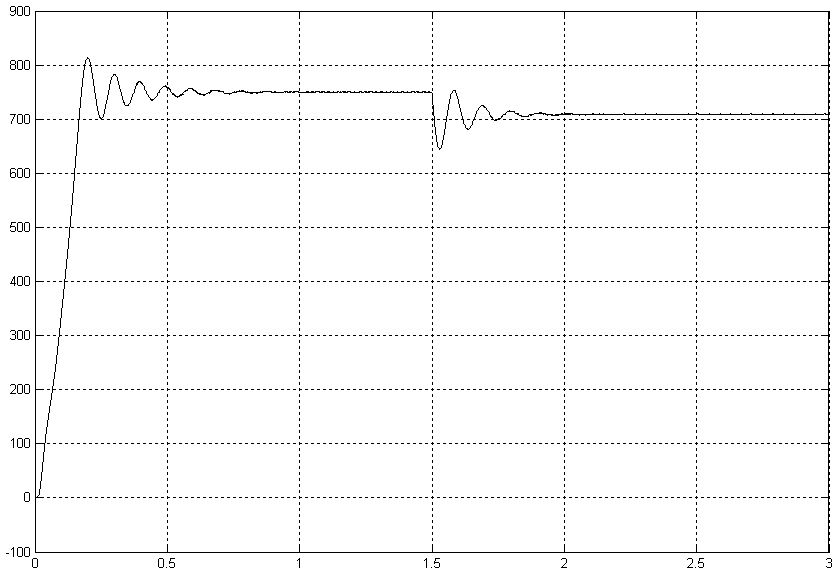
Figure 3.9 - The speed of the engine at Mc=Mном
The graph rate shows that the speed at the same momet load is 720 rev / min.
When the harmonic analysis of the currents of the rotor, stator and the inverter output voltage obtained the following results:
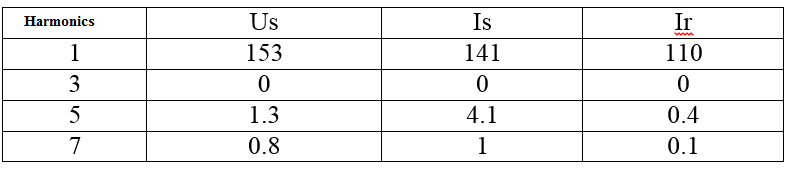
Table 3.3 - Harmonic structure of current and voltage at fc = 25 Hz, fr = 0.9091 Hz.
On the basis of the harmonic content obtained calculate the temperature rise of individual parts of the engine housing. These graphs are shown in (ris.3.10).[8].
Figure 3.10 - overheating of the rotor θCu2 , winding θCu1 and Fe θFe1 stator powered by a TFC with a frequency f = 25Hz"
Animation (the number of frames: 6, number of cycles: 7, volume: 12.6 KB)
tabulate the average temperature obtained by applying a thermal model of the inverter voltage frequency f = 25 Hz currents and curves of the rotor and stator obtained in the TFC-BP.
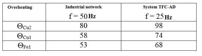
Table 3.4 Overheating of the power industry network and in the TFC-BP.
Next, examine the thermal state of the motor at low voltage inverter frequency f = 10 Hz.
In the process of modeling the system-AD TFC we obtain the following waveform.
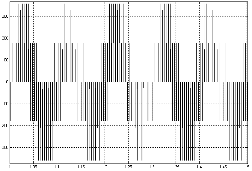
Figure 3.11 - The output voltage of the inverter atFz= 10HzMс= Mrated
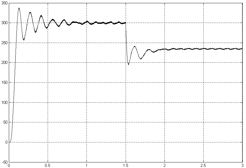
Figure 3.12 - Motor speed at Fz= 10HzMс= Mrated
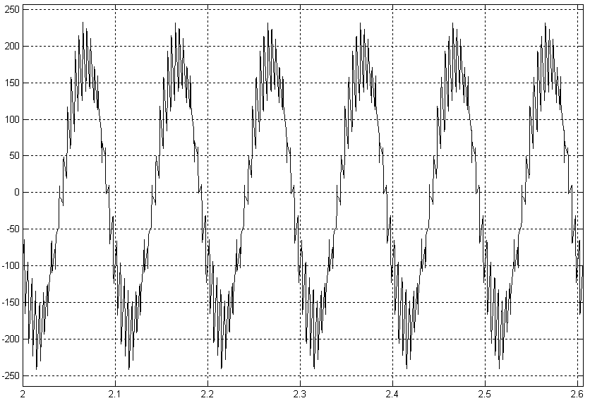
Figure 3.13 - Detail of the stator current Fz= 10HzMс= Mrated
When the harmonic analysis of the currents of the rotor, stator and the inverter output voltage obtained the following results:
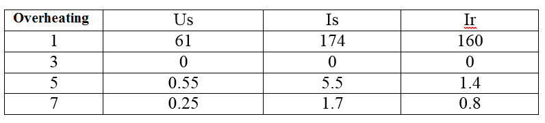
Table 3.5 - Harmonic structure of current and voltage at fc = 10 Hz, fr = 1.2658 Hz.
Based on this harmonic content will do the calculation of excess temperature parts of the engine housing. These graphs are shown in (Figure 3.14).
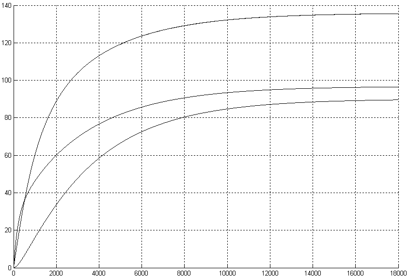
Figure 3.14 - overheating of the rotor θCu2 , winding θCu1 and Fe θFe1stator powered by a TFC with a frequency f = 10 Hz
tabulate the average temperature obtained by applying a voltage to the thermal model of the industrial network with the frequency f = 50 Hz and powered by the voltage of the inverter output voltage at frequencies f = 50, 25 and 10 Hz.[9].
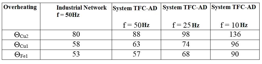
Table 3.6 - The temperature rise of parts of the engine at various frequencies of the supply voltage
Conclusion
Thus, the use of the frequency converter on the basis of autonomous voltage inverter with pulse - width modulation to power the motors in industrial installations of various kinds leads to a change of overheating engine parts, that is causing a violation of its normal thermal mode at rated load.
So the engines that are commercially available to use in such conditions is impossible.
In writing this essay master's work is not yet complete. Final completion: December 2015. The full text of work and materials on the topic can be obtained from the author or his manager after that date. It will be held a series of experiments, research and refinement of the available results.
References
- Г.Г. Счастливый «Нагревание закрытых асинхронных электродвигателей» – Киев «Наукова думка», 1966г.
- Ю.С. Забродин «Промышленная электроника: учебник для вузов» – Москва «Высшая школа», 1982г.
- Костерин С.И., Финатьев Ю.И. – В кн.: «Теплопередача и охлаждение электрических машин» изд. ЦИНТИЭлектропром, Москва, 1963г.
- Шнейдер П. «Инженерные проблемы теплопроводности» Москва, 1960
- Hak J. «Archiv fur Electrotechnik», 1956.
- Постников И.М. «Проектирование электрических машин» Гостехиздат, Киев, 1960г.
- Уэйкерли Д. Проектирование цифровых устройств / Д. Уэйкерли. – М.: Постмаркет, 2002. – Том 2. – 528 с.
- Breeding K. Digital design fundamentals / K. Breeding. – Prentice Hall, 1992. – 446 pp.
- Баранов С.І. Синтез мікропрограмних автоматів (граф-схеми і автомати) / С.І. Баранов. - Л .: Енергія, 1979. - 232 с.