
Abstract
Content
- Introduction
- 1. Relevance of wind energy
- 2. Aims and objectives
- 3. Wind Turbine
- 4. The analyzing system
- Conclusion
- References
Introduction
The object of studying in this article is a wind power plant on the basis of the synchronous generator with permanent magnet and two-link frequency converter.
Currently, wind turbines (windmills) are gaining more and more widespread due rising price of fuel for thermal power plants. Wind turbines are used in autonomous system power supply systems together with classic diesel or petrol generators. It allows to uninterrupted power supply with low fuel consumption.
Common types of alternators, which are used in modern wind turbine systems: asynchronous generator with short-circuited rotor; asynchronous generator with phase rotor; machine dual power; permanent magnet synchronous generator with magnetoelectric excitation; and the synchronous generator with permanent magnets. However, in this paper, a variable rate used directly synchronous permanent magnet generator (SGPM), because it provides better performance due to the higher efficiency and less maintenance, since it has the rotor magnets are not available brushes.
1. Relevance of wind energy
Wind power is unregulated source of energy [1]. Production of wind energy depends on wind power, factor, which is variability. According, the delivery of electricity from the wind turbine to the grid characterized by large uneven, both in daily and in weekly, monthly, annual and long-term perspective.
Modern wind energy has a bunch of problems that affect negatively the improvement of energy-saving efficiency [3]. The most relevant of these are:
- providing the long-term operation of wind power units;
- providing the efficient use of wind energy;
- stabilization of the frequency of electric power, which is produced by wind turbines.
Also, with the growing renewable energy sources the quality of energy which is supplied to the electricity grid becomes important. This problem is particularly acute for wind generators, as the speed of the wind flow is very unstable value and therefore without control power output of wind turbine is unstable too. Hard work is accurate synchronization with grid of the wind turbine, given the changing nature of wind and large masses propeller.
2. Aims and objectives
The general task is to obtain the maximum possible power from the wind farm.
The main technical requirements for wind turbine control system in parallel operation with the grid, as follows:
- operation with specified operating conditions;
- automatic start-up and subsequent synchronization;
- power control and control of the rotor speed;
- control the wind turbine subsystems and equipment, periodic self-control;
- formation and issuing commands to control the elemental wind turbine systems.
The objectives of the management system are:
- the frequency keeping (active power);
- the voltage keeping (reactive power);
- indicators of quality of electric energy;
- protection and automation of wind power plants.
In considering requirements, which we have showed above we should take into account that the wind is characterized by variability of the magnitude and direction, so a single wind turbine power surge should be flatten a large number of devices.
The purpose of this task is the studying the basics of wind energy, methods of control of power output of the wind turbine, the creation of a real working model of the system and the modeling of it. The main objective of this work is to develop a simulation model of the wind power SGPM autonomous system using MATLAB/Simulink package.
3. Wind Turbine
In order to investigate the effectiveness of the energy conversion in wind energy conversion systems, first the available energy stored in the wind needs to be determined [4]. Actually, the energy in the wind can be treated as the kinetic energy of a large amount of air particles with a total mass, m, moving at a wind velocity, Vw. Assuming that all the air particles are moving at the same speed and direction before impacting the rotor blades of the wind turbine, the potential available kinetic energy stored in the wind can be expressed according to the following expression:
 |
(3.1) |
where, E, is the kinetic energy of the moving air particles, and m is the total mass of the air particles, while, Vw, is the velocity of the air particles (wind speed). Since the air particles are moving at a speed, Vw, the total mass, m, of the particles for a period of time, t, can be rewritten as follows:
 |
(3.2) |
where, ρ, is the air density, and A is the swept area of the wind turbine rotor. Here, r, is the radius of the wind turbine rotor. Substituting expression (3.2) into (3.1), the kinetic energy of the air particles can be expressed as follows:
 |
(3.3) |
From expression (3.3), the actual wind power at any instant of time can be represented as:
 |
(3.4) |
where, Pwind, is the potentially available power in the wind. From expression (3.4), we can observe that the wind power is proportional to the cube of the wind speed, which means that a small increase of the wind speed will result in a large increase of the wind power. Moreover, the power can also be increased by enlarging the wind turbine rotor radius since the power is proportional to the square of this rotor radius.
However, the power expressed in expression (3.4) can only stand for the maximum potential power which is available when the wind with velocity, Vw, passes through the swept area of the wind turbine with radius, r. In fact, only a portion of this potentially available power can be captured by the wind turbine. In 1919, a German scientist Albert Betz had tried to express the action of the air particles (the wind) passing through wind turbines [5]. According to Betz's idea, after impacting the rotor blades of the wind turbine, the velocity of the wind decreases form VW to VW2, which means that when the wind passes through the wind turbine blades, there is still some kinetic power left in the wind. The relationship between the power that is captured by the wind turbine and the potential maximum power in the wind can be expressed as follows:
 |
(3.5) |
where, Pturbine is the mechanical power captured by the wind turbine, and Cp is the power coefficient of the wind turbine which can be expressed as follows [6]:
 |
(3.6) |
where
 |
(3.7) |
and
 |
(3.8) |
where, β, is the blade angle, and λ is the tip speed ratio of the wind turbine, while, ωm, is the angular speed of the wind turbine generator. The values of the coefficients (с1 ∼ с6) depend on the type of the wind turbine.
The blade angle β indicates how does the wind velocity impact the wind turbine blades [7]. The blade angle is the angle between the orientation of the blade and the wind velocity vector. When, β = 0, the blade is fully impacted by the wind velocity, and the wind turbine will capture the maximum power in the wind. The blade angle is usually controlled at zero degree when the wind speed is lower than the rated wind speed of the system to ensure a high efficiency of energy capture. When the wind speed becomes greater than the rated value, the power captured by the system will exceed the rated power if the blade angle stays unchanged at zero degree. It will make the generator and the power devices work under higher than rated output, which is harmful to the system if sustained for any length of time. Based on this concern, a control system for the modification of the blade angle according to different wind conditions is needed for the wind turbine [8]. Accordingly, the power captured by the wind turbine can be rewritten as:
 |
(3.9) |
4. The analyzing system
The functional scheme of the simulated wind power system has shown in Figure 1.
Figure 1 – Functional scheme of the wind turbine
(Animation: 6 frames, 5 cycles of repetition, 176 kilobytes)
Synchronous generators with permanent magnets (SGPM) supplies by a two-link frequency converter and from the propeller to it has constantly get negative point. The system has the following control loops: the two outer (speed loop and flow control circuit) two internal (current control loops on axes d and q).
The turbine takes wind speeds Vw, which transmits part of the kinetic energy by interacting with the turbine blades.
The turbine is connected to the shaft, on which there is the torque, with the synchronous generator with permanent magnets (SGPM).
From the generator removed following mechanical characteristics: the angle of rotation θR, rad and shaft
speed ω, rad/s. In the generator mechanical energy is converted into electricity and transfer to the autonomous voltage inverter
(block AIV
), which operates as a rectifier. At this stage, we get uabc voltage and stator current iabc, the value
of which goes to the inverter control system and the calculation of the target rotation speed ωpres.
From AIV
electrical energy is transferred to the DC link, where using a large capacity condenser is collected and transferred to
the active rectifier (block AR
), which operates in the reverse mode as an inverter. Since DC link voltage Ud is removed and transferred
to the active rectifier control system (block CS AR
).
The circuit uses a two-tier frequency converter (inverter), acting as a controlled energy source to generate a voltage in the emerging grid
(current) with the specified value of the main (first) harmonic. To generate and regulate the inverter output voltage uses the principle
of pulse width modulation (PWM). Schemes of AIV
and AR
are made of fully controlled semiconductor power switches.
DC voltage source Ud adjustable and supports two-way exchange of energy with the grid. AR
allows providing of full value two-way
exchange of energy with the grid, while providing a virtually sinusoidal input drive current (current grid).
To control at the first zone, in order to extract at all wind speeds maximum power of experimental by the following table has been made up.
| Vwind, m/s | ω, p. u. | Pel, p. u. |
|---|---|---|
| 1 | 0.06 | 2.2е-04 |
| 2 | 0.15 | 0.0019 |
| 3 | 0.21 | 0.0065 |
| 4 | 0.3 | 0.0152 |
| 5 | 0.36 | 0.0299 |
| 6 | 0.42 | 0.0517 |
| 7 | 0.51 | 0.082 |
| 8 | 0.57 | 0.1226 |
| 9 | 0.63 | 0.1743 |
| 10 | 0.72 | 0.2394 |
| 11 | 0.78 | 0.3186 |
| 12 | 0.87 | 0.4134 |
| 13 | 0.93 | 0.526 |
| 14 | 1 | 0.6568 |
Using these points, we have found an approximated dependent 3rd order ω = f (P), according to which will set the speed to maximize the electric power in the first zone.
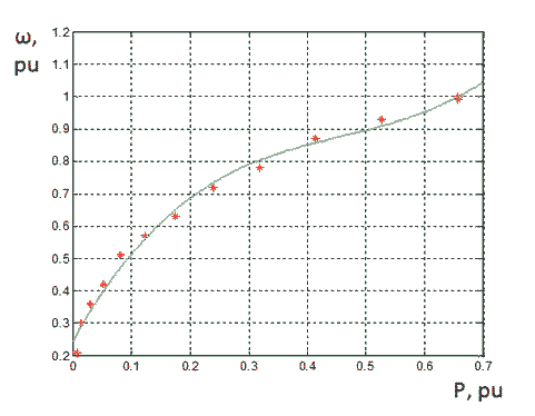
Figure 2 – The approximation of experimental points
ω (P) = 4.405x3 - 6.082x2 + 3.241x + 0.247
The regulation of the second zone by means of the rotation angle β of the blades, which control is implemented using a proportional-integral regulator. When the wind speed is higher than the nominal, it is necessary to pass excess energy. To the PI controller is transmitted information about the current difference between the measured electrical power and the maximum power Pmax* = 0.657 in pu a generator coil, exceeding Pmax* angle β increases by a certain law to maintain maximum power.
Current control loop is executed via the relay current regulators. To RCR
through feedback channel received signals from the current
sensors, which measure the current of each motor phase. These signals are compared with reference signals on the current supplied from
the regulators of speed and flux through the coordinate converters. Setting the current control loop is to select a corridor for RCR
.
To the speed control inputs necessary value rate. From the reference signal through a feedback signal is subtracted from the speed of the generator. The resulting signal comes to the speed regulator operable restriction coordinates.
Conclusion
In this task basics of wind energy have been studied. This paper shows its relevance today. Basic goals and tasks of the wind energy industry were considered. Wind energy is a promising area of science and engineering in economy and ecology point of view, because it is cheapest form of energy, which use renewable resources – wind, and it does not pollute the environment.
Also in the work we present the basic concepts of modeling wind power system wind turbine-SGPM
, which were used to generate
and simulate wind power system.
The functional scheme of the wind turbine was performed, created and simulated using MATLAB/Simulink, to study and review the main electrical control methods which are the basis of works and limit the negative torque to the synchronous generator with permanent magnets. A regulation modeled in the first zone to obtain the maximum possible power regulation and the second zone in order to limit the power limit values.
This master's work is not completed yet. Final completion: May 2017. The full text of the work and materials on the topic can be obtained from the author or his head after this date.
References
- E. V. Kuleshov Permanent-magnet synchronous generator based on the induction machine for stand-alone wind turbine / Dissertation. – Vladivostok. – 2001. – 160 p.
- Horhordin А. V. Optimal management of energy supply system with the use of wind power plant / A. V. Horhordin, M. A Syryh Conference. – Donetsk: DonNTU. – 2013. – 441 p.
- Mahjoub M. F. Prospects for the use of renewable energy sources and choice of design of the generator to work in Western Zahara / Dissertation. – St. Petersburg. – 2000 – 166 p.
- Huang Nantao,
Simulation of Power Control of a Wind Turbine Permanent Magnet Synchronous Generator System
, 2013. - Betz, Albert.
Behavior of vortex systems.
(1933). - T. Sun, Z. Chen, and F. Blaabjerg,
Voltage Recovery of Grid-Connected Wind Turbines After a Short-Circuit Fault,
Proc. of the 29th Annual Conference of the IEEE Industrial Electronics Society, vol. 3, June 20-25, 2004, pp. 827-831. - Ryabov D. Y. Synthesis of fuzzy control position angle of the blades to a wind power installation of the adaptive control system / Dissertation. – Voronezh. – 2009. – 164 p.
- V. G. Chernikov Stabilization of power a wind turbine blade by rotating mechanism / Report. – Donetsk. – 2006 – 26 p.
- Denisov S. V. Autonomous power system with wind generator / Dissertation. – Moscow. – 2001. – 107 p.
- Kuleshov E. V. Permanent-magnet synchronous generator based on the induction machine for stand-alone wind turbine / Dissertation. – Vladivostok. – 2001. – 160 p.
- Kostenko V. I. Conversion equipment / V. I. Kostenko, A. A. Shavelkin. Tutorial. – Donetsk: Donetsk National Technical University. – 2006. – 232 p.
- Pivnyak G. G. The modern frequency-controlled asynchronous electric drives with PWM / G. G. Pivnyak, A. V. Volkov. – Dnepropetrovsk. – 2006. – 470 p.