THE STATOR FLUX AND TORQUE OBSERVER
Source of information: "Robust direct torque vector control system with stator flux observer for PM-SM drives", Record of OPTIM-1996, Brasov, Romania, vol.5.
It is, in general, assumed that the stator currents ia, ib and voltages Ua, Ub (or the d.c. link voltage Ud) are measured. Also, an encoder provides both rotor position Qr and speed feedback in all high performance drives. The observers considered for IMs may be applied here also. Among the real, practical ones we mention the voltage-current, full order observers, Kalman filters and MRAS closed-loop configurations.
The voltage-current closed-loop observer is presented here in some detail.
The voltage model in stator coordinates is

while the current model, in rotor coordinates, is:
![]()
The current in rotor coordinates ![]() is
is
![]()
The stator flux is transformed back to stator coordinates as
![]()
It is evident from the above that the voltage model is plagued by the stator resistance error and the integration drift at low frequencies.
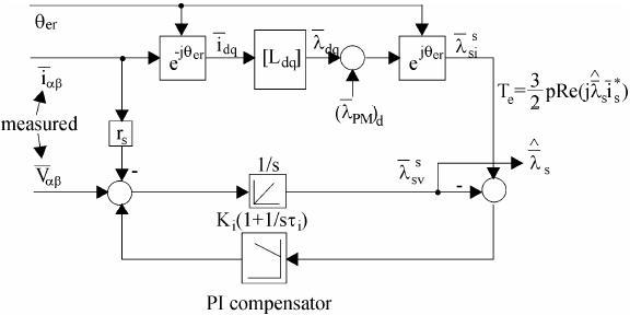
The current model is influenced by parameter detuning (due to magnetic saturation) and by the position error, but it works from zero speed (frequency). A combination of the two with a PI compensator is designed such that the current model is predominant at low speeds, while the voltage model takes over at high speeds (Figure 11.45).
The PI compensator provides for this discrimination. The frequency band for the transition is provided by an adequate choice of Ki and ņi based on the given observer poles w1 and w2, real and negative


Figure 11.45. Voltage and current stator flux observer
Typical values of w1 and w2 are w1= -(3-10) rad/s, w2= -(3-10)|w1|.
The torque is calculated easily from flux and current (Figure 11.45). Providing for low and high speed good performance, DTFC is a strong contender for vector voltage and current control as it is simpler and more robust.