Аннотация
А.В. Светличный, В.А. Соседко Оптимизация энергетических показателей асинхронных электродвигателей. Трехфазные асинхронные электродвигатели (АД) наиболее распространены в промышленности. Большая часть расходуемой в мире электрической энергии используется асинхронными двигателями. Поэтому важно оптимизировать их работу таким образом, чтобы они потребляли минимально возможное количество энергии и обеспечивали экономию энергоресурсов. Различные параметры работы АД исследованы экспериментальным путем и даны предложения по их оптимизации.
The asynchronous (or induction IM) three-phase is the type of motor most widely used in industry. Most of the electrical power consumed worldwide is in fact used by asynchronous motors. So it is essential to optimize the way they operate so that, they consume the lowest amount of energy possible and savings are made in power costs. Different parameters of IM operation were investigated in experimental way and the propositions for optimization of IM performance are given.
Key words: induction motor, efficiency, starting, steady state operation, power consumption, performance optimization.
The asynchronous three-phase electrical motors are widely used in industry and public service. They are the largest energy consumers in the world. That is why a minimization of IM expenditure of energy can give us a big economical effect. One of the ways to do so is to improve the motors construction and the other one is to optimize their performance. The article is devoted to the second direction.
Another important thing is the induction motors effect on the mains supply. During the across-the line start they cause voltage drop, that can affect the others equipment operation. For their work induction motors consume reactive power that loads the cables, transformers with the essential losses. Modern frequency converters bring distortion to the supplied voltage. All above-mentioned negative factors must be minimized to improve efficiency of the whole energy system.
There are different ways of solving the problem [1-3]. Though the field technicians need the simply implemented advices to improve the efficiency of their induction motors operation. The aim of the article is to investigate the IM performance for different powering schemes through the starting and operating modes, as well as on the basis of obtained data formulate guidelines, how to improve the IM performance. For investigation the three phase IM 4А71А4У3 was taken. Its rated power is 0.55 kWt, rated speed 1390 rev/min, rated current 1.7 A, cosφ 0.7, efficiency factor 70.5%.
It was loaded by a centrifugal fan equipped with the control valve to change the load. The schematic diagram of installation is shown at the Fig.1. Agreed notations are: CT1-CT3 – Current Transformers, VS1-VS3 – Voltage Sensors, IS1-IS3 – Instrumental Shunts. QF1, QF2 – Automatic circuit breakers. For the steady-state operation the Lovato DMK 32 multimeter is used to measure voltage, current, power for each phase and their sum. The transient process is recorded with special device RECON 08MC. It records currents and voltages at the frequency 20000 Hz, and makes it possible to process data with common software like Excel and Matlab.
With this installation next variants of motors supply were tested. 1 – direct-online connection. 2 – direct online connection with capacitors. 3 – through the softstarter Altistart (Schneider Electric), 4 – through the frequency converter Unidrve SP (Control Technique). The schemes were investigated in the starting process and steady-state mode of operation. To limit the random errors each starting process was recorded 10 times and the data were statistic processed.
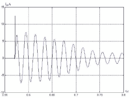
Fig. 2 shows a phase-current trend for direct-online start. The first peak is near 12.5 amps, that is 7 times greater
that a rated current of the motor. It was the biggest peak value, obtained during experiments. The value of the current
peak changes according to the voltage value at the moment of the start and varies from 4 to 7 rated value. When
sensitive protection devices are used in electrical circuits, such short large current peaks can set on the alarm and switch
off the contactor. From the recorded voltage and current diagrams the following parameters were calculated in Matlab:
starting time, average current during starting process, active  and reactive
  energy consumption. The obtained data are presented in Table 1. The start time is near 0.18 sec. that is the low limit for
investigated motor. The average starting current varies from 3.2 to 4.0 of rated current value. Due to the high value of
total current through across-the-line start, magnetic core is essentially saturated. That’s result in high values of reactive
power consumption that is 3.5-4 times grater then the active one. Big value of total starting current causes the big line
loses and voltage drop. The across-the-line start is bad for all components: the main supply, electrical motor and the
mechanical equipment. For the reliable and accident-free operation it is necessary to avoid this starting mode.
energy consumption. The obtained data are presented in Table 1. The start time is near 0.18 sec. that is the low limit for
investigated motor. The average starting current varies from 3.2 to 4.0 of rated current value. Due to the high value of
total current through across-the-line start, magnetic core is essentially saturated. That’s result in high values of reactive
power consumption that is 3.5-4 times grater then the active one. Big value of total starting current causes the big line
loses and voltage drop. The across-the-line start is bad for all components: the main supply, electrical motor and the
mechanical equipment. For the reliable and accident-free operation it is necessary to avoid this starting mode.
Operating mode parameters are shown in Table 2. With the valve adjustment the air flow was changed from zero to maximum possible for fan. The total power and total current remain practically the same, although the active power for air movement changes approximately twice. It means that the losses in supply net remain stable regardless the motors useful charging. It is an inefficient way of operation and some actions must be done to amend the situation. Such action is the application of capacitors to compensate the reactive power consumption.
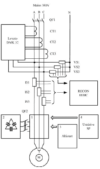
Figure 1 – Test circuit
 |
 |
| Figure 2 – Phase current during direct-online starting | Figure 3 – Phase current during soft starting |
Table 1 – Starting data
| Starting mode | Tstart,s | WР, Wt*s | WQ, VAr*s | Іmax, А | Іaverage,A |
| Direct-online | 0,18 | 39.66 | 156.33 | 8,67 | 6.01 |
| Direct-online with capacitor | 0,19 | 49.35 | 29.43 | 11,58 | 5.75 |
| Soft start | 0,61 | 20.82 | 39.81 | 4,13 | 3.43 |
| Frequency convertor | 0,57 | 45.44 | 73.59 | 4,63 | 2.0 |
| Frequency convertor with network throttle | 0,58 | 38.67 | 34.47 | 1,32 | 1.1 |
For rated mode of operation the calculated total power consumption can be found as
 ,
,where input parameters are taken from motors certificate.
Rated reactive power consumption
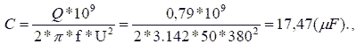
Demanded capacity for compensation is
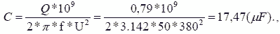
where f is the frequency and the U is rated voltage of mains supply.
Table 2 – Steady-state data
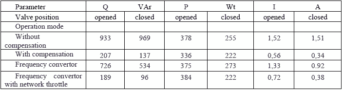
The results of experiments for the variant 2 are presented at the tables 1 and 2. The active power consumption in starting increases a little and the reactive power decreases dramatically for 5-6 times. The maximum starting current in the first moment increases due to the capacitive charging process.
In steady-state mode the results are very good both for idle and operating regimes. The power factor increases, and the total current is 3-4 times less then without the compensation. Due to the squared relationship among the current value and the losses in mains supply the last will decrease by 9-16 times. Such excellent result is obtained for small, under loaded motor. In practice the energy saving will be smaller, but also high to spent money for the compensator installation. To reduce the first peak it is reasonable to connect the compensator after the starting.
To make the starting process better one can use the softstartrer. Such device Altistart was connected to the scheme in the variant 3. You can see from Table 1 that both the maximum and average currents are essentially less then with a direct-online starting. It helps to limit the mechanical shocks in equipment, avoid the voltage drops in the mains and decrease the electrical loses both in the motor and in the line. After such starting process the motors temperature will be appreciably lower then with the direct-online starting. So, we can increase the number of starts per hour if it is necessary. For all unregulated drives it is expedient to use softstartes. It is necessary to keep in mind that capacitors must be disconnected through the starting process to avoid softstarter protection actuation.
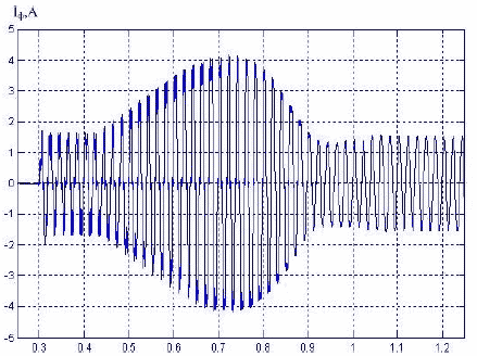
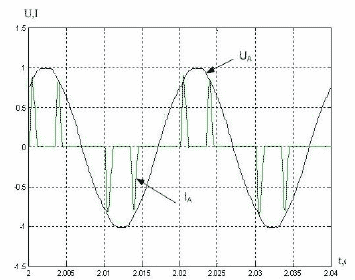
The 4 variant of operation is the supply of induction motor from the frequency converter (FC). The speed Ramp was adjusted to obtain starting time near the softstarting case. If we compare the results in table 1 we can see that the maximum current values for these variants are equal and the average currents are smaller with the FC. That is due to the lower reactive power consumption. But the FC are considerably non-liner consumers that is illustrated with Fig. 4. They do not consume the common reactive power, but bring to the mains essential distortion. To avoid this effect it is necessary to install reactance at the FC input. It helps to approximate the current shape to the sinusoidal one. (Fig.5). Also the energy consumption parameters become better with the throttle installed (Tab. 1,2).
 |
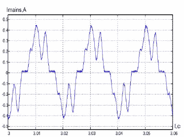 |
| Figure 4 – Phase voltage and current before frequency converter | Figure 5 – Phase current before network throttle |
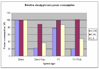
It is interesting to compare the efficiency parameters from all tested variants of IM operation. If we take the acrossthe- line start parameters for 100% the relative diagrams for both operation modes will look as it is presented at diagrams Fig. 6 and Fig. 7. The best results for the starting process are obtained with the softstarter supply. The active power consumption is one half from direct start, and the reactive power consumption makes up near 28% from the base. Taking into account all other abovementioned advantages of soft start, such scheme can be accepted as the best one. Concerning to steady process the simple scheme with capacitors gives the best results. Next are the parameters for the frequency converter, connected through the throttle to the mains supply. Taking into consideration that primary cost of FC with a throttle is vastly higher then the capacitor the withdrawal is obvious. It should be mentioned that when reactive power is compensated, the total energy consumption is determined with the useful load at the shaft. So, when we use the valve for productivity adjustment, compensated motor will take from the mains only corresponded necessary active power. For vast majority of pumps and fans simple scheme with capacitors is the most economically sound.
 |
 |
| Figure 6 – Diagram of relative energy consumption during starting process | Figure 7 – Diagram of relative steady process power consumption |
Resume
- For the vast majority of induction current motors the starting process must be realized with the softstarter.
- After the finishing of starting process and softstarters shunt, the capacitors should be connected to compensate reactive power to minimize the energy consumption and losses in the supply circuits.
- The frequency converters contaminate the mains with high-frequency components, so they must be connected through throttles for reduction of their harmful impact.
Список использованной литературы
- Nene V.D. Optimal Tracking of the Dinamic Performance of an Induction Machine/ V.D. Nene / Electric Machines and Electromechanics, 1982. №7. - Pp. 27-34.
- Subramanian Manoharan. Review on efficiency improvement in squirrel cage induction motor. //Journal of ELECTRICAL ENGINEERING, VOL.60, NO.4, 2009, pp. 227-236
- K. Ranjjth kumar, D. Sakthibala, Dr. S. Palaniswami. Efficiency Optimization of Induction Motor Drive Using Soft Computing Techniques // International Journal of Computer Applications. NO 1, 2010, Article 2.