Hardware infrastructure of remote laboratory for experemental testing of FPGA based complex reconfigurable systems
Milos DRUTAROVSKY, Jan SALIGA, Ingrid HRONCOVA,
Department of Electronics and Multimedia Communications, Technical University of Kosice,
Park Komenskeho 13, 041 20 Kosice, Slovak Republic, E-mail: {Milos.Drutarovsky, Jan.Saliga}@tuke.sk
Ixonos Slovakia s.r.o., Sturova 27, 040 01 Kosice, Slovak Republic, E-mail: Ingrid.Hroncova@ixonos.com
The paper describes a remotely accessible laboratory system that allows performing experiments remotely from anywhere across the Internet via web interface as well as locally in the classroom. The system is aimed at courses of advanced digital design and signal processing using complex Field Programmable Gate Array (FPGA) platforms. It is a powerful tool that allows students the full access to laboratory equipments and FPGA platforms remotely from any remote terminal with any common web browser and standard remote desktop interface. The system consists of Altera development FPGA kits, suitable instrumentation and a PC running an interactive LabView based software including a Graphical User Interface (GUI). A logic analyzer, a digital storage oscilloscope, and a pattern and arbitrary waveform generators are part of the workplaces to enable testing and debugging of FPGA applications under development.
Keywords: FPGA, soft processor, signal processing, remote laboratory, hardware experiments, LabView, distance learning
Training in advanced courses of Programmable Logic Devices (PLDs) requires access to expensive hardware equipments. The high cost of these instruments along with time consuming development process in individual students’ projects required within the educational process creates a significant bottleneck. The restricted university budget does not allow building of a several such development and test stands, and time schedule and university security conditions restrict the time when the stand can be accessible for students locally in a laboratory.
A solution of this problem could be to build a virtual or remote laboratory. The virtual laboratory is generally based on sets of software models that represent objects or systems in a given abstraction level. Some of these are web based, others are just toolsets that are standalone applications. The students can use them at any time and in any place. The only problems here are with the accuracy of the behavior of the simulator representing a real system and speed of detailed simulation for complex systems. Often the real objects differ from their abstract model and most of them cannot represent all details of real features and behavior of the simulated object.
Unlike virtual laboratories, the remote laboratory is based on real hardware [28], [12], [11], [16], [26], [25]. Such laboratories are very convenient and effective for hardware design laboratory course. Hardware experimental environment is usually treated as an exclusive resource for single user usage. However, the actual test run time is rather short and most of the time is wasted leaving these costly resources idle. The combined use of FPGA/PC connected test hardware and PC-controlled measurement equipments such as Logic Analyzer (LA), Digital Storage Oscilloscope (DSO), etc. may open a way to develop a remote multi-user time-sharing system for hardware experiments, where students at remote terminals can perform actual experiments using real hardware equipments and tools remotely from home or students residence.
An example of a remote laboratory system can be Nokia Remote Device Access (RDA) [25]. It is a service that allows developers to test their mobile applications and services remotely on various Nokia devices based on Symbian OS. The main features of the service are remote controlling of a device, installing and running applications, transferring files, and analyzing log files in real-time. RDA is an Internet-based solution.
The aim of this paper is to describe hardware (HW) and software (SW) considerations necessary to build a remote web-based laboratory for FPGA development and testing. The proposed remote laboratory is a first step to the teaching of advanced courses for students of the course PLDs at the Department of Electronics and Multimedia Communications, TU Kosice. It is expected that this course will demonstrate also advanced topics from DSP and microcontroller area.
Modern large FPGA devices have capacity equivalent to millions of equivalent gates and contain big amount of embedded multipliers, Digital Signal Processing (DSP) blocks, hierarchical memory subsystems, hard cores etc. Designs based on a single FPGA device can currently contain complex soft 32-bit RISC processors (even in the form of small on-chip networks), complete signal processing blocks (e.g. for Software Defined Radio), or other Systems on a Programmable Chip (SoPC). Development of such complex designs requires access to the target hardware platform for experimental testing.
A typical FPGA design flow can be divided into the following steps:
- Project description and specification.
- Design entry through schematic capture and/or Hardware Description Languages such as VHDL or Verilog.
- Functional simulation and design verification.
- Design synthesis.
- Design implementation, post place and route simulation.
- FPGA hardware reconfiguration.
- Design verification: testing and debugging.
These steps can be divided into two main groups. Stages 1 through 5 can be accomplished using only Electronic Design Automation (EDA) software tools. Stages 6 and 7 require access to the real FPGA hardware.
A typical FPGA design process is an iterative process that requires compilation of a complete design and testing/detection of errors. The compilation process can take several tenths of minutes for complex systems. Testing on real HW platform after successful functional simulation of short time segments (timing simulation of complete complex systems is far beyond the capabilities of current EDA simulation tools) is nowadays the only practical testing solution. A typical example is testing of HW and SW components of embedded soft processor with custom HW peripherals/coprocessors [15].
Generally, real HW testing requires only a short time for processing on the target HW. Standard testing HW contains at least a target FPGA board, JTAG interface to a host computer, and the host computer. More advanced HW can contain LA, DSO, and a Pattern Generator (PG). All these HWs are rather expensive and they are mostly required only for a short time.
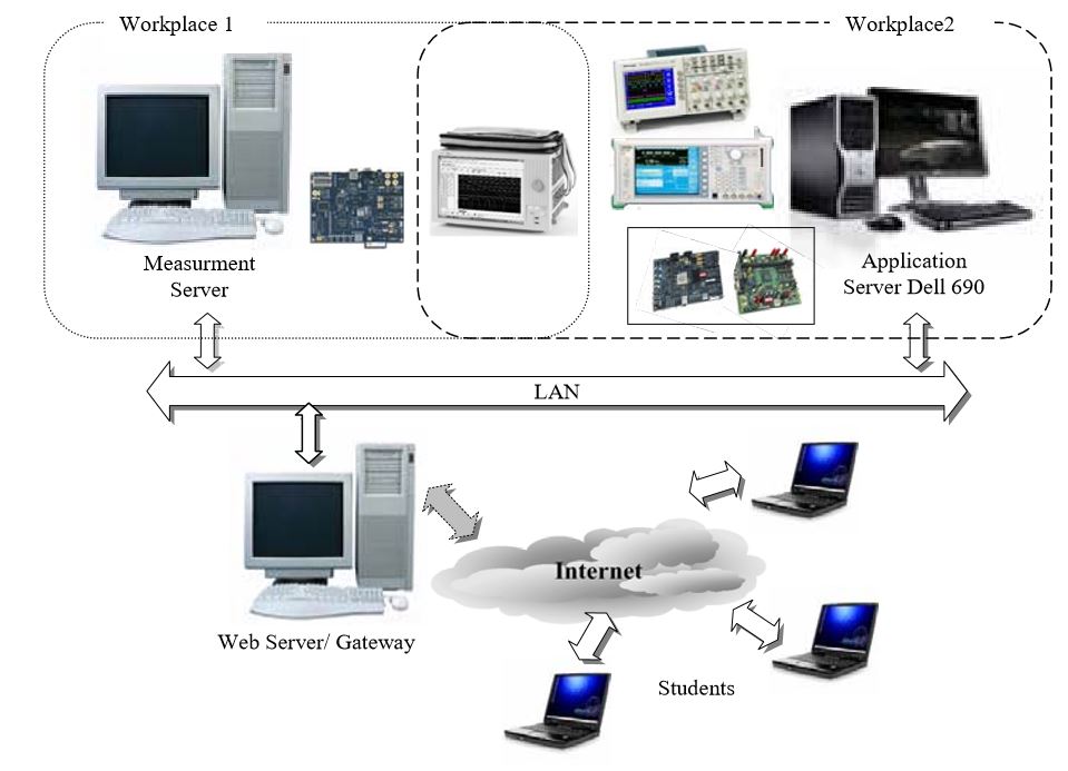
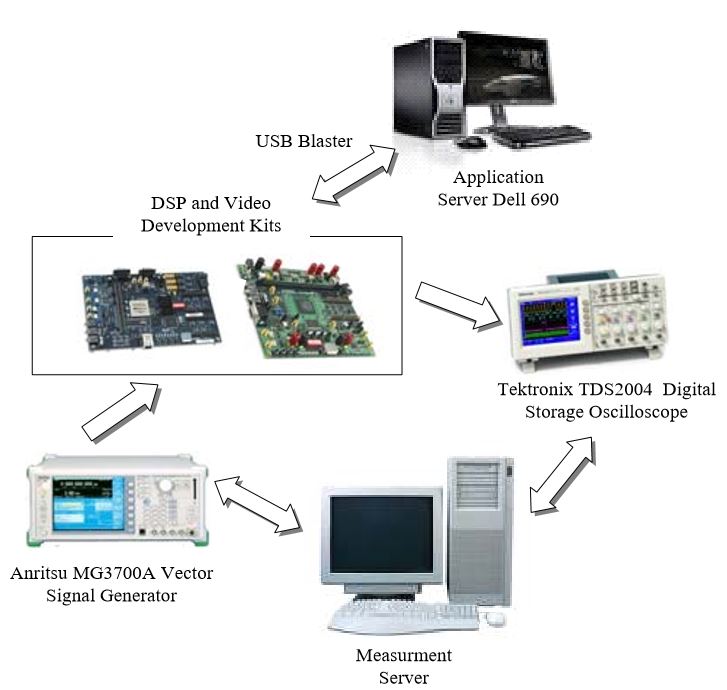
The main idea behind the project is to provide an access to the expensive HW and to enable using it remotely through Web and remote desktop interfaces. The remote laboratory, accessible from anywhere through the Internet connection, has been built according to the general methodology to control instruments through Internet. Basic structure of the laboratory is shown in Fig. 1.
Because the measurement equipments and test units are very expensive and it is difficult for a student to occupy them right on the place for a longer period of time we have decided to start building a remotely accessible hardware laboratory for FPGA programming and testing.
The core of the system is built on:
- Web and Measurement Servers with LabView based control software,
- a set of Altera FPGA Development Kit boards,
- Agilent 16822A Logic Analyzer – 68 Ch 4 GHz Timing 500 MHz State Logic Analysis, with 48 Channel Pattern Generator [1],
- Tektronix TDS2004 4-channel Digital Storage Oscilloscope [27],
- Anritsu MG3700A Vector Signal Generator (VSG) [13],
- EDA tools Application Server DELL 690 workstation, 4-core Xeon CPU, 8 GB memory.
The measurement instrumentations (LA and VSG) are linked to the Measurement Server via LAN (Ethernet) that creates the local communication backbone. The DSO vendor has implemented into DSO only USB, that is why the communication with DSO has to use this interface. From the measurement point of view the main bottleneck of the Ethernet and USB is the precise group triggering and synchronization in the measurement system in comparison with optional GPIB (IEEE-488) but we do not expect any extreme triggering requirements in the suggested system. Moreover, the local LAN is not overloaded by general communication what decreases possible delays in control command delivery. In the future optional additional requirements on the precise group timing can be solved by an external triggering offered by each instrument.
The instruments are serving for two independent measurement stands:
- Digital electronics test stand that enables performing tests on FPGA is equipped with LA with build-in pattern generator.
- Mixed analog and digital electronics test stand that enables performing tests on DSP and video kits is equipped with VSG and DSO.
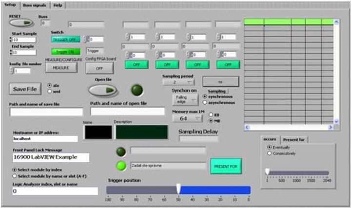
The software consists of two sets of independent applications for FPGA and DSP based kits, respectively. These applications have to enable the students to have a complex and comprehensive view of performed measurement task and a possibility to set up simply the conditions of measurement, e.g. parameters of stimulus signal, etc. The required simplicity is the reason why the control of instrumentation was partially restricted to the functions that are really needed for the given tasks. Moreover, to allow remote controlling of the instrumentations across the Internet the specialized software tools implemented on the Measurement Server had to be developed. Fig. 2 shows an example of custom developed GUI (client side) available for restricted setting of LA via Web Server [17].
The software has to fulfill the following requirements:
- To set up the instrumentations according to the requirements of a user.
- To acquire measured data from LA and DSO, to process and prepare it for delivery to the end user in a convenient format, e.g. graph, listing, data file, etc.
- To accept, process, and upload user data to the pattern and arbitrary generators.
- To run, trigger, and synchronize the performance of the current measurement task.
LabVIEW by National Instruments [18] has been chosen as the software development platform for the software application. The main reasons for this decision are:
- Simple graphical programming environment that enables very fast and effective development of an application for measurement and signal processing. It is easy to learn, and is supposed to be a standard in the measurement system programming. This fact opens the way how to attract and involve also students of final years of study into the development of some remote laboratory components, e.g. within their theses, etc.
- Simple to use instruments drivers offered by the instrument vendor and National Instruments that significantly simplify the programming.
- Integrated functions for Internet data transfer using various data transfer protocols and built-in Web Server.
- Rich libraries for data processing and analysis.
The instruments drivers developed by vendors unfortunately use different methods of data/command transfer among the Measurement Server and the instrument itself. The LA by Agilent requires communication based on COM automation objects, methods, and properties programming while DSO by Tektronix and VSG by Anritsu use common VISA-based access [29]. To simplify the complex programming even using the instrument drivers we have decided to use only a restricted variety of COM automation components to transfer the configuration XML-based file that is edited on the Measurement Server according to user measurement requests and measurement data files.
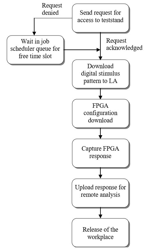
The proposed HW infrastructure will provide an access to expensive HW in time multiplex (job scheduler) [16], [26]. It should enable to a remote user to load his/her FPGA project via web interface into a buffer where it would wait when the HW resources will be free. As soon as the HW is available, the job is processed and the results of HW responses are sent back to the user for off-line analysis of the testing results.
Basic features expected of the job scheduler are:
- Automatic submission of executions.
- Interfaces to monitor the executions.
- Priorities and/or queues to control the execution order of unrelated jobs.
Job scheduling enables seamless access to the HW and SW resources to several concurrent users. It enables more effective use of the HW equipments.
This section provides description of Altera FPGA kits based workplaces and measurement/testing equipment functionality available for testing of the supported FPGA designs. Remote laboratory provides access to two separated FPGA workplaces as shown in Fig. 1.
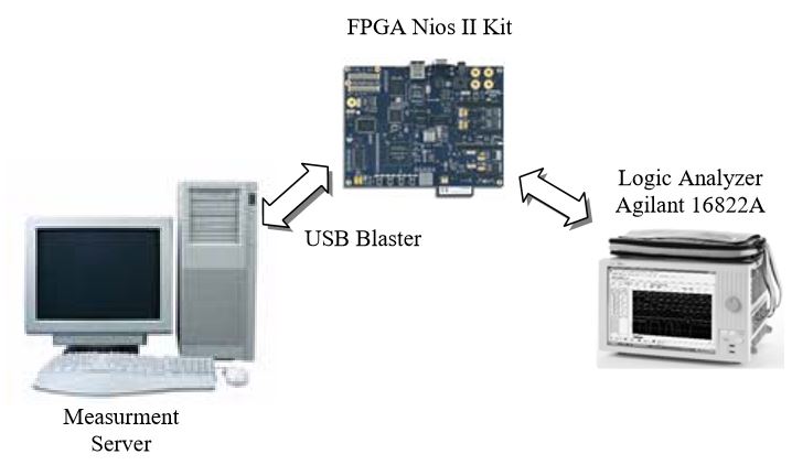
Workplace 1 provides access to the NIOS II Development Kit, Cyclone II Edition (ALT1) [5] and LA with pattern generator functionality. Block diagram of the Workplace 1 is shown in Fig. 3.
The ALT1 kit is based on the low-cost Altera Cyclone II EP2C35F672 FPGA device that is used in many typical cost sensitive applications. It is connected via Altera download cable – USB blaster [10] directly to the Measurement Server.
The USB-Blaster download cable [10] interfaces a USB port on the Measurement Server to the Altera FPGA mounted on a printed circuit board. The cable sends configuration data from the remote user to a standard 10-pin JTAG header connected to the Cyclone FPGA. LA is connected to the selected measurement points of the Cyclone FPGA device and NIOS II board buses. LA is used mainly for capture of FPGA responses during testing phase. Pattern generator of LA can be optionally used for generation of user definable digital stimulus sequences.
The Workspace 1 supports standard iterative FPGA design and testing flow shown in Fig. 4 and provides HW platform for the following types of experiments:
- Development and testing of general digital logic designs. All EP2C35 Cyclone FPGA device resources (logic elements, embedded memories, PLLs, ...) are available to the remote user. Such designs can vary from very simple up to complex standalone designs.
- Development and testing of designs based on predefined standard soft 32-bit RISC NIOS II processor [6] designs. All NIOS II board resources (FLASH, SDRAM, UART, Compact FLASH, ...) are available to the remote user. Quite complex hardware and software designs can be tested (e.g. embedded uClinux based applications) with relatively small user design effort. They can clearly demonstrate advantage of FPGA usage in embedded applications.
- Development and testing of NIOS II based designs extended with custom peripherals [14] embedded into EP2C35 Cyclone FPGA device. Such designs represent the most complex designs based on hardware/software co-design.
Workplace 2 enables access to the DSP Development Kit, Stratix Edition [3] and Video Development Kit, Cyclone II Edition [9]. These kits provide target FPGA platforms for testing DSP functionality of modern FPGA devices. Both Altera FPGA devices (Stratix II EP2S60F1020C4 and Cyclone II EP2C70F672C6) contain embedded multipliers that are crucial for embedded DSP.
The kits offer the following analog interfaces:
- Two 12-bit (14-bit), 125-million samples per second (MSPS) analog-to-digital (A/D) converters.
- Two 14-bit, 165-MSPS digital-to-analog (D/A) converters.
- VGA digital-to-analog converter (DAC).
These interfaces together with the high performance FPGA resources allow testing of quite complex DSP algorithms embedded into FPGA devices. DSP designs based on available Altera Intellectual Property (IP) blocks are the typical designs tested on Workplace 2. Design flow of characteristic IP based designs are supported by licensed Altera Quartus II [8] EDA tool, selected IP Megafunctions supported by Altera DSP Builder [2], and Matlab running on the Application Server. Access to these resources is performed by standard remote desktop access with dynamic access control implemented on the Web Server.
Powerful VSG can be used for generation of complex synthesized analog waveforms used in common testing DSP applications. Waveform generation can be based on predefined waveforms stored on the VSG hard disk or user defined by using Matlab tools [23]. The 4-channel DSO can capture analog waveforms generated by testing DSP applications. Both of measurement equipments can be controlled by Measurement Server and captured data can be sent to the remote user for off-line analysis.
Block diagram of the Workplace 2 is shown in Fig. 5.
The Workspace 2 supports advanced DSP IP block FPGA design and testing flow shown and provides HW platform for the following types of experiments:
- Development and testing of Finite Impulse Response (FIR) and Infinite Impulse Response (IIR) filters embedded into target FPGA devices.
- Testing of real time processing of selected digital modulation (AM, FM, OFDM, …). A set of predefined experiments will be used as a standard HW testing approach.
- Basic processing and generation of video-signals. A set of predefined experiments will be used as a standard HW testing approach.
- Development and testing of custom DSP applications. Due to complexity of such designs, it is expected that these will be performed within Master and, in particular, PhD theses.
These experiments allow filling the gap among specialized theoretical subjects given at the Department of Electronics and Multimedia Communications, TU Kosice, and functionality of current modern FPGA devices. IP – based development of DSP applications enables to build up quite powerful applications with reasonable development effort. It can also increase motivation of students to follow this branch of study more deeply.
Standard FPGA designs will be done off-line by free Altera EDA Quartus II tool [7]. This tool is available free off charge and a remote user can download and license this software for local usage. Designs for the both of Cyclone boards can be done with this software.
The powerful DELL Application Server with remote desktop access was added in order to support also more advanced designs with licensed software tools available at the Department of Electronics and Multimedia Communications:
- Fully licensed Altera Quartus II EDA tool provides a possibility to use also Altera Stratix FPGA based designs.
- A set of licensed Altera IP blocks can be used for building advanced DSP based applications.
- Nios II C-to-Hardware Acceleration Compiler [4] can be used for automatic C to hardware transformation.
- Matlab [22] simulation environment can be used e.g. for definition of custom waveforms or other advanced DSP experiments.
- Matlab Signal processing toolbox [21] can be used for simulation of advanced DSP applications.
- Filter Design Toolbox [20] can be used for design of FIR and IIR filter parameters.
- EDA Simulator LinkTM MQ for Mentor Graphics Modelsim [19] can be used for high-level connection of Matlab with Modelsim simulation environment.
- High performance Modelsim simulator [24].
These tools are currently fully licensed for educational and research purposes at the department and access to them will be controlled by access policy implemented on the Web Server/Gateway. These tools represent current state of the art for design and testing of modern embedded FPGA based designs with Altera FPGA devices. Remotely accessible Application Server enables to use this advanced technology within standard educational and research activities.
The paper presents hardware aspects of the remote FPGA laboratory for development and testing of complex reconfigurable systems which is being built up at the Department of Electronics and Multimedia Communications at the Technical University of Kosice. The laboratory is still in the process of development. Currently, all equipments and evaluation boards are already functional and basic connectivity of equipment is tested. In parallel typical FPGA based experiments are prepared and integration works will start in the next months. A lot of work will be done within Master theses of our students. This allows us to involve our students more deeply into this advanced technology what is our main goal.
This work has been done partially within the KEGA 3/5238/07 project Remote Laboratory for Experimental Testing of Complex Reconfigurable Systems/Circuits Based on FPGA Circuits
of Slovak Ministry of Education and it was also partially supported by the Science Grant Agency of Slovak republic (Grant No. 1/0103/08).
The authors also thank to Altera which provided us with Quartus II EDA tool in the form of floating licenses within the framework of University and Higher Education programs and to National Instruments, the office in Prague, for some recommendations and advisements.
- AGILENT TECHNOLOGIES, Logic Analyzer 6822A, http://www.home.agilent.com/agilent/
- ALTERA DSP Builder, http://www.altera.com/support/ip/dsp/ips-dspbuilder.html
- ALTERA DSP Development Kit, Stratix Edition http://www.altera.com/products/devkits/altera/kitdsp-2S60.html
- ALTERA Nios II C-to-Hardware Acceleration Compiler, http://www.altera.com/products/ip/processors/nios2/tools/c2h/ni2-c2h.html
- ALTERA Nios II Development Kit, Cyclone II Edition, http://www.altera.com/products/devkits/altera/kitnios-2c35.html
- ALTERA NIOS II soft processor, http://www.altera.com/products/ip/processors/nios2/
- ALTERA Quartus II Web Edition Software, https://www.altera.com/support/software/download/altera_design/quartus_we/dnl-quartus_we.jsp
- ALTERA Quartus II, http://www.altera.com/support/software/sofquartus.html
- ALTERA Video Development Kit, Cyclone II Edition, http://www.altera.com/products/devkits/altera/kitvideo-cyclone2.html
- ALTERA, USB Blaster download cable – User Guide, April 2008, pp. 1-24.
- ANDRIA, G. – BACCIGALUPI, A. – BORISC, M. et al.: Remote didactic laboratory "G. Savastano," the Italian experience for e-learning at the technical universities in the field of electrical and electronic measurements: Overview on didactic experiments, IEEE Transactions on Instrumentation and Measurement, Vol. 56, Issue 4, Aug. 2007, pp. 11351147.
- ANDRIA, G. – BACCIGALUPI, A. – BORISC, M. et al.: Remote didactic laboratory "G. Savastano," The Italian experience for e-learning at the technical university in the field of electrical and electronic measurement: Architecture and optimization of the the communication performance based on thin client technology, IEEE Transactions on Instrumentation and Measurement, Vol. 56, Issue 4, Aug. 2007, pp. 1124-1134.
- ANRITSU, Vector Signal Generator MG3700A, http://www.eu.anritsu.com/products/default.php?p=183&model=mg3700a
- DRUTAROVSKY, M. – FISCHER, F. – SIMKA, M. – CELLE, F.: A Simple PLL-based True Random Number Generator for Embedded Digital Systems, Computing and Informatics, Vol. 23, No. 5-6, 2004, pp. 501-516.
- DRUTAROVSKY, M. – SIMKA, M.: Custom FPGA Cryptographic Blocks for Reconfigurable Embedded NIOS Processor, Acta Electrotechnica at Informatica, No.2, Vol.4, 2004, pp. 33-39.
- FUJII, N. – KOIKE, N.:A Time-sharing Remote Laboratory for Hardware Design and Experiment with Shared Resources and Service Management, Proc. of the ITHET 6th Annual International Conference, Juan Dolio, Dominican Republic, July 7-9, 2005, session T2B5 – T2B10.
- KALO, K.: Test Bench with Remotely Controlled Logic Analyzer, Diploma Work, Department of Electronics and Multimedia Communications, FEI TU Kosice, May 2008, pp.1-63.
- LABVIEW, National Instruments, http://www.ni.com/labview
- MATLAB EDA Simulator Link for Mentor Graphics ModelSim, http://www.mathworks.com/products/modelsim/
- MATLAB Filter Design Toolbox, http://www.mathworks.com/products/filterdesign/
- MATLAB Signal Processing Toolbox, http://www.mathworks.com/products/signal/
- MATLAB, http://www.mathworks.com/products/matlab/
- MG3700A Vector Signal Generator MATLAB Application, Antrisu Application Note, pp.1-50
- MODELSIM Verification Environment, http://www.mentor.com/products/fpga_pld/simulation/index.cfm
- NOKIA, http://wiki.forum.nokia.com/index.php/Remote_Device_Access#RDA_description
- PASTOR, J. S. – GONZALEZ, I. – LOPEZ, J. – ARRIBAS, F. G. – MARTINEZ, J.: A Remote Laboratory for Debugging FPGA-Based Microprocessor Prototypes, Proceedings of the IEEE International Conference on Advanced Learning Technologies (ICALT'04).
- TEKTRONIX, Digital Storage Oscilloscope TDS2004, http://www.tek.com/products/oscilloscopes/tds1000_ tds2000/
- UTS:Engineering Remote Laboratory Program, http://remotelabs.eng.uts.edu.au/vvtour/fpgaabout.html
- VXI plug&play Systems Alliance documents VPP 4.3.X, http://www.ivifoundation.org/specifications/
