
Abstract
Содержание
- Introduction
- 1. Choosing a device design and creating a 3D model
- 2. Selection of equipment
- 2.1 Comparison of servo drives
- 2.2 Selecting a microcontroller and comparing it with others
- 2.3 Characteristics of DC-DC converter
- 3 Creating a layout
- 3.1 Implementing the power of the device
- 3.2 Implementing Remote Management
- Сonclusions
Introduction
Designing robots is a time-consuming process, so we do not see them everywhere in our homes. But maybe the situation will change with the appearance of a new way of producing them – 3D printing.[1] With the use of this technology, the cost of creating and assembling is minimal and no waste. Nicholas Bartlett of the Harvard School of Engineering and Applied Sciences says that 3D printing is unique, because it helps to control the internal parts of the robot. He and his team used printing technology to make a soft robot that can inflate their feet and jump up to a height of six times its own. However, according to Paul Beardsley of Disney Research in Zurich, the technology does not provide a reliable material structure. His team used 3D printing to create the prototype wheels of a four-wheeled bot, which rides the walls. The researcher says that it is too early to make extensive use of 3D printing capabilities in creating robots, at least for now, as the parts can deform in the sun or not be waterproof. Until the printed 3D objects become more durable, a material such as aluminum remains the best option. Although in situations where fast fix is needed, 3D printing can be the optimal solution. For a long time there has been a discussion about robots that would carry a 3D printer with them and with it could quickly print a tool or part needed to work on the spot. This will allow the robots to adapt to any situation. who would carry a 3D printer with him and with his help could quickly print a tool or part needed to work on the spot. This will allow the robots to adapt to any situation. who would carry a 3D printer with him and with his help could quickly print a tool or part needed to work on the spot. This will allow the robots to adapt to any situation.
At the same time, printing becomes popular as a means of manufacturing prostheses. Company Poppy Project
distributes 3D drawings for modular prostheses, and people around the world can print prostheses on the cost of materials - all figures are in the public domain, which significantly reduces the cost of their cost.
Such a merger of technologies may give impetus to the spread of mobile robots around the world.
When manufacturing our robot, we took advantage of this benefit of scientific and technological progress and fully utilized the technology of 3D printing.
Design and development of the walker can be divided into:
Development:
After completing the tasks, the debugger was debugged and the first start of the device was made. We will dwell in more detail on the fulfillment of the tasks set out above.
1 Select a device design and create a 3D model
When choosing a design, we initially settled on a four-legged robot with three degrees of freedom for each leg (describe degrees of freedom). This, in our opinion, made it possible to simplify the design and manufacture. Such a walker was made by us and tested. When choosing a design, we initially settled on a four-legged robot with three degrees of freedom for each leg (describe degrees of freedom). This, in our opinion, made it possible to simplify the design and manufacture. Such a walker was made by us and tested. However, these tests showed that the design was unstable. Therefore, in the construction of the walker, two legs were added that make it possible to obtain a more stable structure, that when walking a six-robot always has three points of support and more evenly distributed mass. Also, the transition to a six-legged design simplified the writing of the algorithm of operation. For the basis of our 3D model, the model of a four-legged robot from the internet was taken and processed, in which we were beaten with two legs that helped us achieve the necessary stability.
2 Equipment selection
We selected and ordered equipment from us based on: the necessary technical characteristics, dimensions and price indicators. The results of the analysis of the market showed that the optimal for the three indicators are two drives Tower Pro MG90 and Tower Pro MG90S micro servo 14g. These drives are distinguished by reducer material, torque, load capacity and price. For lighter and heavier robots, you can use Tower Pro MG90 based on your own experience, I can say that this drive is not as powerful and wear-resistant as the MG90S, but it has a higher quality of components and assembly. The conclusion was made on the basis of the fact that out of 18 MG90S ordered by us, the two servos turned out to be defective and in order to not stop for a long time, the available MG90 was taken at that time.
2.1 Comparison of servo drives
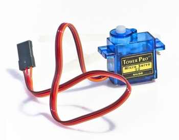
Tower Pro SG90 micro servo 9g - light and high quality microservo for a low price. Easy management with Arduino, AVR, PIC, ARM and other microcontrollers.2]
Tower Pro MG90
Characteristics:
Equipment:
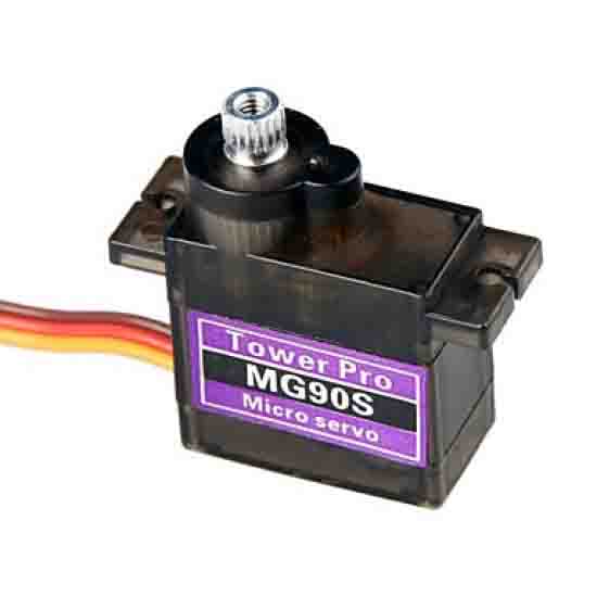
It is possible to use Tower Pro MG90S micro servo 14g – light and high-quality microservo.[3]
Tower Pro MG90S
ОIt differs from the Tower Pro SG90 with a completely metal gearbox. Easy management with Arduino, AVR, PIC, ARM and other microcontrollers.
Characteristics:
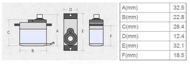
The dimensions of the servo drive Tower Pro MG90S
These drives are distinguished by reducer material, torque, load capacity and price. For lighter and less loaded robots, you can use the Tower Pro MG90 based on your own experience, it can be argued that the MG90 drive is not as powerful and wear-resistant as the MG90S, but it has a higher quality of components and assembly. The conclusion was made on the basis of the fact that out of 18 MG90S ordered by us, the two servos turned out to be defective and in order to not stop for a long time, the available MG90 was taken at that time. They were installed on the extreme segments of their legs and perfectly coped with their task.
2.2 Selecting a microcontroller, comparison.
For control, we chose between two microcontrollers Arduino Uno and Arduino nano v3. Arduino Uno R3 is the most popular board from the Arduino series. The standard form factor of the Uno card allows you to connect to it a huge number of different shild-boards, extending the platform's capabilities.
Arduino Uno R3 is built on the basis of the microcontroller ATMega328P-PU. As a USB-UART converter, the ATMega16U2 chip is used. The capacity, memory size and number of pins Arduino Uno R3 is sufficient for most tasks that arise in amateur electronics.[4]
Characteristics:
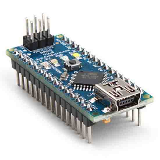
Arduino Nano v3.0 is a compact board built on the microcontroller ATMega328.5]
Arduino nano v3.0
Functionally Arduino Nano is similar to Arduino Uno, but is made in a compact form factor and is not compatible with Arduino shilds, but is compatible with standard breadboard and breadboard-boards. Also does not have a separate power connector. The connection to the computer is via the Mini-USB connector.
Characteristics:
Also, the elements necessary to create a prototype were ordered: (conductors, prototyping board, increasing DC-DC converter)
2.3 DC-DC converter characteristics
It is worthwhile to take a closer look at the characteristics of a DC-DC converter. [6] For the project, a DC-DC converter Step-Up boosting LTC1871 100W was chosen. Voltage converter boosting the universal with a digital display and the ability to adjust the voltage you need from 3.5 to 35 volts. Adjustment is carried out by a trimmer resistor. The digital display displays the set input and output voltage. The input voltage must be between 3 and 35 volts. The device remembers
the configured output voltage and regardless of the input voltage will be converted to the one you need. The maximum output current is up to 6 amps.
Specifications:
3. Creating a layout
Starting with the choice of material for the details of the layout, a lot of scientific papers and articles were studied, the authors of which wrote that aluminum is optimal for making robot parts, which is confirmed by the words of Paul Beardsley from Disney Research, he said: Until the printed 3D objects become more durable, Material such as aluminum remains the best option
. [1]
Drawing on the articles read the trial layout, was made of aluminum. But in the process of assembly it became clear that the parts are easily bent and badly glued with hotmelt. This was the first drawback of the created layout. After the assembly tests were carried out and several test inclusions showed us that arduino nano is not capable of providing stable operation of 18 servos. This was the second drawback in the manufactured layout. To eliminate the identified shortcomings:
All these changes were made to the design of the device, and debugging was carried out, for which the algorithm of control of the walker was developed. The developed program allowed to work out the basic movements (forward, backward, to the right, to the left).
Debugging has shown that the design and control algorithm are designed correctly. The first starts were made using a laboratory power supply, which limited the possibilities of movement. Consequently, the next task was to create an independent power source. The abundance of wires connecting different elements did not allow to get a real view of the device. The solution of these problems was the next stage of work on the device. To reduce the links, it was necessary to replace the existing arduino nano controller with the arduino mega. This is due to the fact that Arduino MEGA2560 has more discrete outputs (more than 18), [8] it will allow us to control all servos independently. Previously, using arduino nano, we did not have such an opportunity.
The Arduino MEGA2560 Pro Mini controller is a compact microcontroller board based on the Atmega2560. In its essence, it is a simplified analog of Arduino Mega, which makes it possible to reduce the cost of the project. ATmega2560 operates at 16 MHz (0.5% tolerance). [7]
This controller will be installed in the printed circuit board, which is an amplifier and power distributor along the elements of the device, which will simplify the wiring diagram.
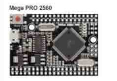
Arduino MEGA2560 Pro Mini
3.1 Realizing the power supply of the device
There are two options for implementing the power of the robot. The first option is to connect several lithium batteries in parallel, thereby increasing their capacitance and current, and also adding a boost converter to this circuit. Since the robot from the laboratory power supply consumes at 6V from 2.5-3.5A, the converter must be taken with a margin in power.
The second option is to connect 2-3 batteries in series and lower the voltage received by the converter. I consider this method to be ineffective, since converters available on the market have low efficiency, heat up very much and on the sale it was not possible to find a model suitable for the rated current. Analyzing both versions of the prototype, Li-ion 18650 batteries and a DC-DC converter will be used as a power source.
After making the necessary changes in the design, we obtained a better model. The tests were carried out under different operating conditions, that is, the model worked out the programmed movements. The tests carried out showed that the device fully meets the stated tasks specified in the design. However, in this state, the model does not have a remote control function, which is important. Thus, the next task was to create a device for remote control of the walker. Looking at the currently available Bluetooth modules and their characteristics, it turned out that they are practically the same as the transmission speed. In our device this parameter is not important. As such a device it was decided to use the Bluetooth module HC-05.
3.2. Implementing Remote Management
Module Description
This module is a board measuring 2.7x1.4 cm, with 34 pins in 1.5 mm steps located around the perimeter of the board, [9] and has an antenna at one end:
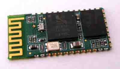
Bluetooth-module HC-05
On the board is the BC417 chip from Cambridge Silicon Radio, which provides hardware support for the Bluetooth 2.0 + EDR (Enhanced Data Rate) stack, and the 8Mbps (1MB) Excel ES29LV800DB-70WGI flash memory that stores the firmware and settings. With the original Chinese firmware, the module can work in two modes: a simple radio extender UART
and control AT commands. In the first case, everything is extremely simple – you turn on the module, connect to it from a computer or other device that can create a COM port by Bluetooth, and send data to this port. In the second mode, you can control the module through AT commands like AT+COMMAND
– for example, the AT+NAME?
allows you to find out the name of the module, but more on that later.
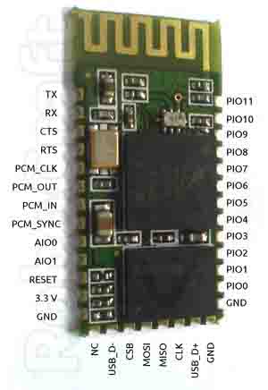
Module circuit
The module is powered from 3.3 V, but its I / O lines can work with 5-volt logic, which allows to connect its UART to Arduino. It should be noted that the step between the terminals of the module is 1.5 mm and for prototyping you will have to solder the wiring or create a printed circuit board. We stopped at the second option.
Module circuit
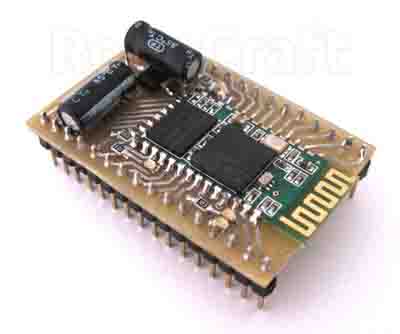
<The printed circuit board helps us to use the module on the prototyping boards because it soldered a single comb with a standard pitch and all the necessary radio components are soldered for quick and easy connection to the microcontroller, for example: there is a 3.3 V stabilizer on the board, so you can power the module with the standard Arduino 5 V by connecting the power to the terminal marked 5V. Schematic diagram of the board:
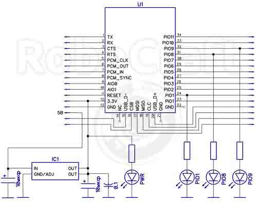
Circuit diagram of the board
The board is ready, we will start working with the module. We put the breakout on the development board and connect it as follows:
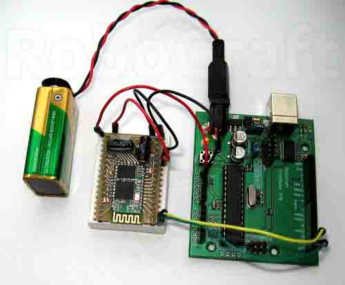
Assembled device
The introduction of Bluetooth on the above scheme will allow us to manage the manufactured device with android smartphone.
Conclusions
In our work, the process of creating a spider robot is described in full step-by-step. All components and devices used in this project are listed. The validity of the correctness of the selected elements and devices has been confirmed experimentally. This made it possible to create a working prototype of a robot on the basis of which it is possible to create a mass of useful devices for investigating an inaccessible environment for the human being. He can also become an indispensable assistant for electricians. Another one is his use as a stand for teaching students the basics of robotics.
List of sources
- 3D печать предвещает быстрое развитие робототехники // imolodec [Электронный ресурс]. – Режим доступа: http://imolodec.com.... свободный.
- Сервопривод Tower Pro MG90 // mini-tech [Электронный ресурс]. – Режим доступа: http://mini-tech.com.ua..., свободный.
- Сервопривод Tower Pro MG90S // mini-tech [Электронный ресурс]. – Режим доступа: http://mini-tech.com.ua..., свободный.
- Arduino Uno R3 // mini-tech [Электронный ресурс]. – Режим доступа: http://mini-tech.com.ua..., свободный.
- Arduino Nano v3.0 // mini-tech [Электронный ресурс]. – Режим доступа: http://mini-tech.com.ua..., свободный.
- Преобразователь DC-DC Step-Up LTC1871 100W // ledshop [Электронный ресурс] – Режим доступа: http://ledshop.vn.ua...,свободный.
- Arduino MEGA2560 Pro mini // arduino-ua [Электронный ресурс]. – Режим доступа: http://arduino-ua.com..., свободный.
- Arduino Mega 2560 R3 // mini-tech [Электронный ресурс]. – Режим доступа: http://mini-tech.com.ua..., свободный.
- Bluetooth модуль HC-05 // robocraft [Электронный ресурс]. – Режим доступа: http://robocraft.ru..., свободный.