
Abstract on the theme of master's work
Content
- Introduction
- 1. Relevance of the topic
- 2. The purpose and objectives of the study, the planned results
- 3. Review of literary sources
- 3.1 Fundamentals of radio wave technology
- 3.2 Overview of the FlySky FS-iA10B radio receiver and the FlySkyFS-i6X radio transmitter
- 3.3 Analysis of the market of possible components
- List of sources
Introduction
Over the last decade, technology has made a big leap, most of the systems of large and small electric drives have changed, thus obtaining new lines of activity. So, a small electric drive, the main part of which is DC collector motors, replenished with brushless motors. These engines have become a «panacea» in the construction of multi-rotor systems and stabilization systems. These distribution motors are very good and have high overload capabilities, and, depending on the purpose, can maintain high smoothness and accuracy of travel. Such systems are very important in the long-term future, since they allow the transport of various kinds of cargo through the air, and also create bionic prostheses on their basis. If in the case of prosthetic devices, engine control, namely data transmission controls, can be carried out using wires, then in multi-rotor systems, which provide permanent communication with the weapon, it is possible only via a wireless channel.
1. Relevance of the topic
The main disadvantage of multi-rotor systems is high current consumption, but in the foreseeable future the problem will be solved by using more energy-intensive batteries. The unresolved issue remains the maintenance of a constant wireless connection with the object, especially in situations where the object will be removed for a long distance. Of course, you can specify the route of movement on the control points, and with the help of modern navigation methods, but that to direct the way the operator will need to solve an emergency landing or change the route of movement? How to access and manage the object? Such an opportunity can only provide high-quality radio communication. Thus, combining with the problem of high power consumption, it becomes a problem of uninterrupted remote control of the object.
2. The purpose and objectives of the study, the planned results
The goal of this work is to find means of providing communication with the object and constructing a transmitter capable of providing an acceptable quality of communication with the object. To achieve this goal, it is necessary to solve a number of tasks, namely:
- Explore available methods and technologies for wireless data transmission;
- Identify the most appropriate ways to transfer data;
- Identify the necessary components for the implementation of wireless data transmission;
- Conduct market analysis and availability of these elements;
- Construction of the current prototype of the receiver and transmitter;
- Programming and debugging of projected devices.
Planned results of the work done:
- Obtaining an active device for receiving and transmitting data over wireless communication;
- Obtaining an acceptable quality of communication for managing multi-rotor systems at medium distances.
3. A review of the literature
3.1 Fundamentals of radio wave technology
Wireless data transmission can be carried out using infrared, laser and radio wave radiation.
To achieve stable and, importantly, a powerful signal that allows data transmission to tens of meters, the third method is best suited, namely the transmission of data by means of radio waves, since this method has several advantages, namely:
- More stable operation in conditions of reduced visibility;
- Due to a wide range of radio frequencies, the possibility of data transmission over long distances;
- Ability to amplify the transmitted signal.
First, you need to understand what a radio wave is?
Radio waves – are electromagnetic waves, whose frequencies are conditionally limited to frequencies below 3000 GHz , propagating in space without an artificial waveguide[1][2]. Radio waves in the electromagnetic spectrum range from extremely low frequencies up to the infrared range. Taking into account the classification by the International Telecommunication Union[3][4] of radio waves over ranges, electromagnetic waves with frequencies from 0.03 Hz to 3 THz, which correspond to a wavelength of 10 million kilometers to 0.1 millimeter, are referred to radio waves
Broadly speaking, radio waves are all possible wave processes of the electromagnetic field in equipment (for example, in waveguide devices, in microwave integrated circuits, etc.), in transmission lines and, finally, in natural conditions, in a medium separating the transmitting and receiving antennas[5].
РRadio waves, being electromagnetic waves, propagate in free space at the speed of light. Natural sources of radio waves are lightning flashes and astronomical objects. Artificially created radio waves are used for stationary and mobile radio communications, broadcasting, radiolocation, radio navigation, satellite communications, the organization of wireless computer networks and other countless applications.

Radio wave emission scheme (animation: 8 frames, 10 cycles, 91.1 kilobytes)
Depending on the value of frequency (wavelength) radio waves are referred to a particular range of radio frequencies (wavelength range). These ranges can be classified as follows[6]:
| Frequency range | Frequency name | Wavelengths | Name of waves | Application |
|---|---|---|---|---|
| 3 – 30 Hz | Extremely low (ELF) | 100 Mm – 10 Mm | Decameters | Connection with submarines, geophysical research |
| 30 – 300 Hz | Ultra-low (ULF) | 10 Mm – 1 Mm | Megameters | Connection with submarines, geophysical research |
| 300 – 3000 Hz | Infra-low (ILF) | 1000 km – 100 km | Hectokilometers | Connection with submarines |
| 3 – 30 kHz | Very low (VLF) | 100 km – 10 km | Myriometric | The service of exact time, radio communication with submarines |
| 30 – 300 kHz | Low (LF) | 10 km – 1 km | Kilometers | Radio broadcasting, ground-based radio communication, navigation |
| 300 – 3000 kHz | Medium (MF) | 1000 m – 100 m | Hectometric | Earth-wave radio broadcasting and radio communication |
| 3 – 30 MHz | High (HF) | 100 m – 10 m | Decameter | Radio and ionospheric radio, over the horizon radar |
| 30 – 300 MHz | ОVery high (VHF) | 10 m – 1 m | Meters | Broadcasting, radio and direct tropospheric wave radio |
| 300 – 3000 MHz | Ultra-high (UHF) | 1000 mm – 100 mm | Decimeter | Television, radio, tropospheric and direct waves, mobile phones, radio, UHF-therapy |
| 3 – 30 GHz | Ultrahigh (UHF) | 100 mm – 10 mm | Centimeter | Radiolocation, Internet, satellite broadcasting, direct-wave satellite and radio communication, wireless computer networks |
| 30 – 300 GHz | Extremely high (EHF) | 10 mm – 1 mm | Millimeter | Radioastronomy, high-speed radio relay communication, radiolocation (meteorological, weapon control), medicine, satellite radio communication |
| 300 – 3000 GHz | Hyperhigh (HHF) | 1 mm – 0,1 mm | Decimetallometers | An experimental «terahertz camera», recording an image in a long-wave IR |
For this project, meter, decimeter and centimeter waves are suitable. It should also be noted that the longer the wavelength, the greater the distance it can overcome, but the data transfer rate in this case decreases, directly proportional to the increase in wavelength.
Thus, for the frequency range of 136 – 174 MHz, the data transfer rate will reach 19.2 Kbps, with a transmission range of 50 to 70 km, and for the 2.4 GHz band, the transmission speed will increase significantly and will reach 54 Mbps, however the transmission range will be significantly reduced.[7][8]
Based on the above, the most optimal solution for achieving the objectives will be the use of a range of ultra-high frequencies. But you can not use any frequency from this range, because the main part of the range is allocated for special needs of life, for example:
- Navigation;
- Aviation;
- Radio and television broadcasting;
- Radio communication of special services;
- And etc.
To the authorized, specially allocated for civilian needs, the following frequencies:
| Name | Bandwidth | Description |
|---|---|---|
| «11-meter», Citizens’ Band – civilian range | 27 MHz | With an authorized transmitter output power of up to 1000 milliwatts |
| «70 cm», LPD – Low Power Device | 433 MHz | There are 69 channels for portable radios with an output power of up to 10 milliwatts |
| PMR – Personal Mobile Radio | 446 MHz | 8 channels for portable radio stations with an output power of not more than 0.5 W |
Also, for civil purposes, you can use a narrow spectrum of frequencies, starting at 2.4 GHz.
At the moment, the main part of radio equipment uses the frequencies of this spectrum, however, at 2.4 GHz the radio waves are highly prone to deformation of the environment, so the waves can be influenced by the material from which the walls of the room are made, so when using this frequency it is desirable to provide a direct «visibility» between receiver and transmitter.
3.2 Overview of the FlySky FS-iA10B radio receiver and the FlySky FS-i6X radio transmitter
The developed device will be based on existing devices. As a reference radio transmitter, FlySky's radio equipment, model FS-i6X, will be used. This equipment has the next parameters:
- Number of channels: 6 – 10;
- Frequency range: 2.408 – 2.475 GHz;
- Power of signal: 20dBm;
This equipment has the next form:
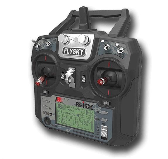
Radio transmitter FlySky FS-i6X
Radio equipment has 2 control sticks, which in turn control 4 channels. Physically, the stick represents two variable resistors connected in the following construction:
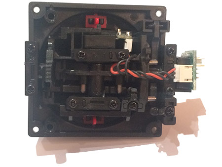
Stick, construction
The variable resistors are marked with b5k-60, the rotation angle is limited to 60 degrees and the resistance is 5kOhm.
The internal structure of the control equipment has the next form:
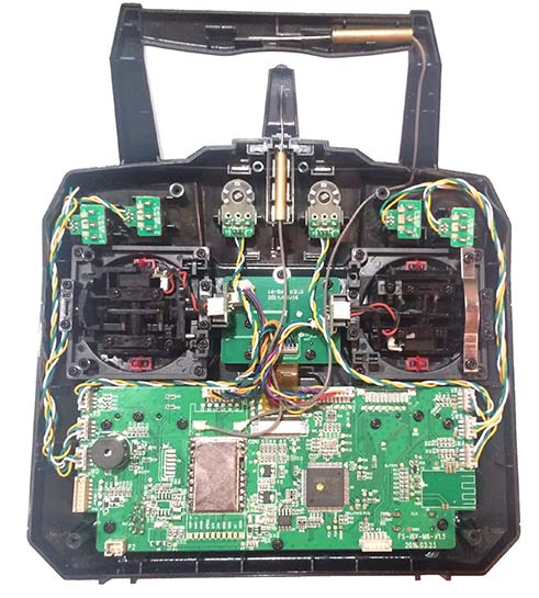
Radio transmitter FlySky FS-i6X construction
The command center of this equipment is the microcontroller STM32F072, which processes the data of the sticks and toggle switches, encodes and transmits them as data packets via a radio module (in the photo it is shielded by a metal plate) to the receiver. This radio module is equipped with two antennas, located perpendicularly. Such a technical solution is justified by the possibility of the signal from the transmitter to cover a large area of space. These antennas are in the form of a pin with a quarter-wave cup.
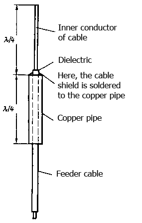
The construction of a rod antenna with a quarter-wave cup
A quarter-wave symmetrical glass allows to achieve full matching of the antenna with the cable and to get rid of parasitic high-frequency currents in the braid of the cable, which increases the efficiency.[9]
As a reference radio receiver, a FlySky receiver model FS-iA10B will be used. This receiver has the following form:
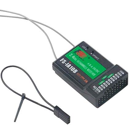
Radio receiver FlySky FS-iA10B
The function of the radio receiver is to receive and convert the received data into a PWM signal, which is subsequently transmitted to the controller of the multi-rotor device. This radio receiver has two whip antennas and their mutual arrangement is also desirable to make perpendicular.
3.3 Analysis of the market of possible components
To implement this project, it is necessary to design and assemble control equipment and a radio receiver, this requires the next minimum of electronic components:
- Microcontroller;
- Radio module;
- 4 variable resistors.
Microcontroller for control equipment and receiver is ArduinoProMini, because this board has a compact size and a relatively simple structure for building programs in the AdruinoIDE. In the future this microcontroller will be replaced by a more powerful one to increase the computing power.
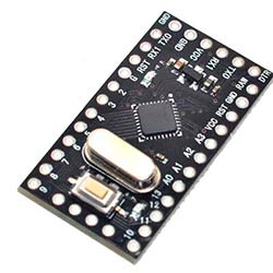
ArduinoProMini
As a radio module on 2.4 GHz, you can use the popular module nRF24L01 or its enhanced version nRF24L01+PA.
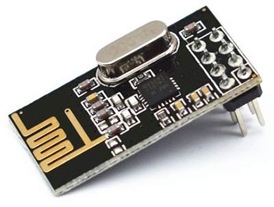
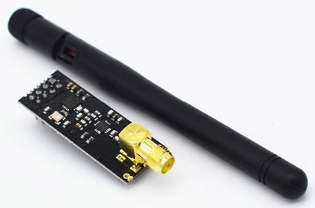
Radiomodules nRF24L01 and nRF24L01+PA
This radio module is able to develop a radiation power of 18 dBm. A version without an antenna is capable of covering a line-of-sight distance within a hundred meters, a version with an amplifier and an antenna capable of covering a line-of-sight distance within 1 kilometer.
However, when there is an obstacle in the path of the signal from the transmitter to the receiver, the characteristics of these modules deteriorate strongly.
As a radio module, you can also use modules on a carrier frequency of 433 MHz. Such modules are more stable when working under conditions of «poor» visibility and are capable of covering a distance greater than modules with a frequency of 2.4 GHz.
One option is the HC-12 module on the SI4463 chip. It has the next advantages:
- Maximum power: 20 dBm;
- The maximum distance to be covered when transmitting data on a regular antenna: up to 1000 meters;
- The module is equipped with a separate microcontroller STM8, which takes care of all the initializing functions of the SI4463 chip;
- Communication interface with microcontroller: UART;
- Ability to connect an external antenna.
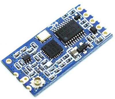
Radio module HC-12
This radio module, by its characteristics and functionality, is most preferable to use.
As variable resistors, it is not necessary to use resistors with an angle of 60 degrees, suitable and ordinary variable resistors of 5 kOhm, the difference in the resistance angle can easily be changed in the program code.
List of sources
- Регламент радиосвязи. Статьи. – Швейцария, Женева: МСЭ, 2012. Статья 1.5.
- ГОСТ 24375-80 Радиосвязь. Термины и определения [Электронный ресурс] – Режим доступа: ГОСТ свободный.
- Рекомендация ITU-R V.431-7. Номенклатура диапазонов частот и длин волн, используемых в электросвязи. 2005.
- Геннадиева Е. Г., Дождиков В. Г., Кульба А. В. и др. Краткий энциклопедический словарь по радиоэлектронике и радиопромышленности / Под ред. В. Н. Саблина. М.: Диво, 2006. С. 276.
- В. В. Никольский, Т. И. Никольская. Электродинамика и распространение радиоволн. М.: Наука, 1989. С. 467.
Радиоволны
// Википедия, статья [Электронный ресурс] – Режим доступа: ru.wikipedia.org свободный.- Практика радиосвязи как она есть.[Электронный ресурс] – Режим доступа: Хабрахарб свободный.
- Диапазоны частот беспроводной передачи данных [Электронный ресурс] – Режим доступа: Tadviser свободный.
- Ремонт и изготовление новой антенны аппаратуры РУ на 2,4 ГГц.[Электронный ресурс] – Режим доступа: Паркфлаер свободный.