The article is focused on the issue of the automatic tool change (ATC). The discussed topic can be onsidered at present to be the most relevant for the group of machines from the category of milling centres. The pressure for productivity, efficiency of the whole manufacturing process, reliability and, last but not least, safety, leads manufacturers to design and install modern equipment for the implementation of automatic tool change which fulfil the most strict requirements. Today, the most problematic area of used equipment for ATC is the manipulator ensuring the change of the tool between the spindle and the magazine. The kinematic arrangement and constructional solution ofindividual elements very significantly influence the dynamism of the whole process of change of the tool. Therefore, the work is focused just to the resolution of the issue of manipulators. The main results of the solution are theconstruction design of several types of manipulators, some of which were implemented within the project 1.2.4 in the Brno workplace RCMT (Research Centre of Manufacturing Technology) in the form of testing stands. Simulation models were created for selected types; for whose verification results of measurements from real equipment were used. On the basis of the solution of this issue, further key problem was identified related not only to the process of replacement, but also the complex problem of the service life of the spindle. It concerns the problem of the force originated during the process of the clamping of the tool. The article outlines possibilities for further research concerning the influences of these forces on the service life of the spindle (mainly service life of the bearing groups of the bedding of the spindle).
Keywords:automatic tool change, ATC, automation, tool interface, simulation model, LabView, Adams
1. Introduction
For many years the effort of mankind has been towards the elimination of difficult, monotonous and hazardous work and its replacement by the work of machines. Machines as inanimate objects do not need rest or vacation and they do not protest against shift work. They perform requested activities precisely, quickly and reliably. At first sight it is possible to say that machines are the absolutely ideal change for man in the manufacturing process.Unfortunately it is not so. The complicacy of the human mind is outside the possibility of current technology which results in the necessity of keeping the human factor in the manufacturing process. A man, by his intelligence, ability to evaluate and react to outside impulses, is an important element in the whole manufacturing process. A machine continues to be in position of “breathless” Golem, who executes the commands of a man.
It is necessary to point out that, without machines in the form of manufacturing equipment, as well as in the form of automation technology, mankind would not be at the stage it is at present. Despite the fact that wetrivialized the machine into the role of an inanimate helper, we have to state that it fulfils this role excellently. It is even possible to dare to say that machines are exceptional in many ways and irreplaceable. For example, inthe area of automation technology it is possible to consider that machines are irreplaceable from the viewpoint of speed, precision, bearing capacity, as well as from the viewpoint of reliability and safety. In the spirit of our previous statement, it can be said that automation technology is a necessary and often integral part of all modern manufacturing machines. Their necessity is evident in the strategy of the European Committee CECIMO and CIRP assembly. These strategies contain, among other things, requirements for an increase in the productivity of machine tools, and the issue of automation closely relates to this fact. The fact that these two important organisations are dealing with this issue documents the principal character of the issue. In relation to the above-mentioned demands and strategies, the project ‘1.2.4 Fast automatic manipulation’ was solved by the Brno workplace of RCMT(Research Centre of Manufacturing Technology).
2. Analysis of existing status
2.1 Basic division
Automatic tool change is the most common example of the automatic manipulation functions of manufacturing machines and equipment. This can be seen in the fact that its application for manufacturing equipment has the greatest influence on the reduction of side times and the automation of the manufacturing process. Compared with other automation elements, the influence of ATC on non-productive times is more significant. This is mainly shown by the modern concept of universal machine centres which are able to perform a large volume of technological operations per each clamping of the work piece [Housa 1985]. The frequency of tool change is significantly greater than, forexample, the number of replacements of work pieces, and also the total time for the implementation of all tools is more important. Depending on the demands of individual manufacturing machines and equipment, a large number of types of automatic tool change have been developed which differ both in their principle, and in the construction solutions of individual producers. As a basic and universal model it is possible to use the following divisions:

Within the resolution of the project, a relatively wide search was performed of producers of machines, as well as producers of ATC solutions, which resulted in a request for the development of new types of manipulators which would provide the potential to speed up and improve the quality of the ATC process if these solutions were technologically available from the viewpoint of their production. So, the effort is to weaken the dominant position of manipulators using globoid cams, the production of which requires quite advanced technologies which cannot be considered commonly available for producers of machine tools.
2.2 System analysis of ATC issues
The system analysis and synthesis [Janicek 2007] represent a complex tool for detailed analysis of a problem situation or abstract object with the use of structured and formalized methods. Our effort was to implement this procedure into the solution of the ATC issue and to use its potential for the resolution of partial problems, as well as the whole issue. The intention was to propose by means of these modern procedures a complex solution which would fully correspond to our requirements.
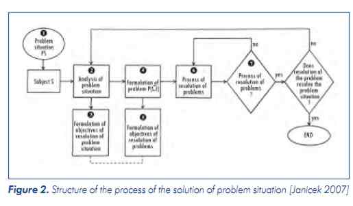
Fig. 2 presenting the process of the solution of the problem situation shows the importance of the process of analysis of the problem situation. The correct performing of this analysis influences the formulation of the system , as well as the problem. The correctness of these initial stages of the solution of the problem situation significantly influences the process of resolution and the relevancy of achieved results. An incorrect initial formulation of the problem may lead us to a solution which does not resolve the problem situation or resolves it unsatisfactorily. So, it is necessary to concentrate on the following initial statuses with the aim of achieving a formulation of the problem which will lead to the resolution of the problem situation. In this manner it is possible to achieve time, as well as financial, savings.
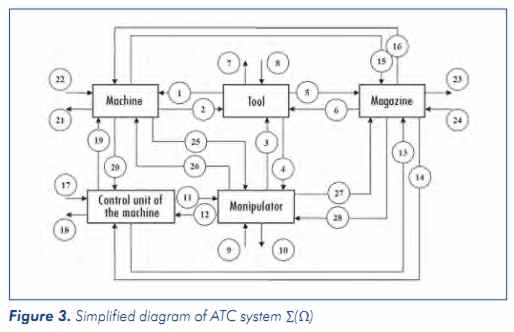
On the basis of the above-mentioned facts it is evident that the first step of the resolution is the formal creation of the system , which in our case will represent an abstract object created by individual elements and the system of important values. First of all, it is necessary to decide which objects will be included in system and in this relation to define the system of essential values. For a block diagram, see Fig. 3. displaying thesystemwith individual objects and relations which occurred in an actual system. This simplified diagram was then used for definition of the system of relation values where it was also decided which relations were important for resolution of the problem and which were not important.
3. Construction design of manipulators
On the basis of the system approach to the solution of the stated problem, we started the design of a whole series of conceptual arrangements of manipulators from the viewpoint of drives (rotary, transitional / electric,hydraulic, etc.), and in relation to the type of the drive and elements transforming the driving force to the required movement. The effort was to verify possibilities of various mutual combinations enabling the implementation of ATC. However, from the viewpoint of practical application it looks as if the most suitable are variants using electric drives in the form of conventional asynchronous engines or mainly new servo-drives [Poppeova 2002]. This fact is mainly stated by the high efficiency, reliability, small estate dimensions and ecologic character of the operation and particularly the simple character of the control. Below is a description of a proposed solution.
3.1 STD-25
This concerns equipment serving for the implementation of experimental tests in the area of the development and research of ATC systems. The proposal for the construction solution of the testing stand is derived from the inspiration of the cooperation in the area of development of an actual ATC system implemented by the Brno workplace of RCMT and a Czech producer of machine tools.
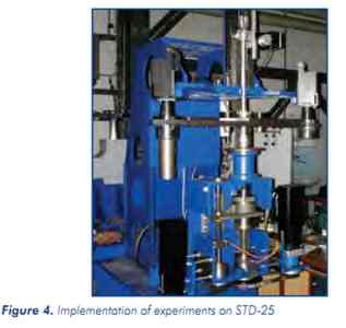
The stand is designed to be easily modified, enabling experiments with the application of various drives, gears and methods of control of manipulation movements. By selecting a suitable construction, this equipment can present a universal character. For the implementation of experiments with other types of drives or partially also a kinematic arrangement, it is possible to use great parts of them, in particular, more complicated components (divided box,arm, main shaft, etc.). The stand is also equipped with a measuring sub-system which gives a direct measurement of the position of the arm of the manipulator, providing exact information about the position or the speed and acceleration. So, we are not predicated during the verification of simulation models on less exact data from indirect measurements with the use of integrated sensors of drives.
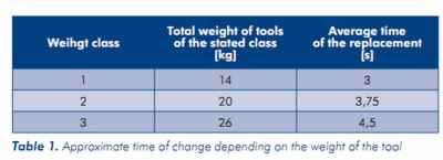
The experimental tests on STD-25 provided precious data about the possibilities of this concept of the manipulator; see Tab. 1. Our efforts also resulted in the gathering of comprehensive characteristics and data about the behaviour of the manipulator which would allow the verification of simulation models created in MSC.Adams environment.
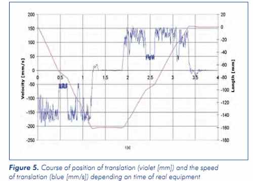

On the basis of data gathered during the experiments, it was possible to create and verify simulation models which allow us to state with sufficient precision the behaviour of real equipment. The only thing which these modelscannot predict is, for example, the impulse movements during the translation of the arm. However, this fact does not significantly influence the global behaviour of the manipulator as a whole.
3.2 Compact manipulator
On the basis of knowledge and experience achieved during the development and experimental tests on STD-25, the compact manipulator ATC was designed. It was important to retain all advantages of the existing solution, i.e. mainly its simplicity and the possibility of producing this equipment even with restricted production possibilities (it is not necessary to produce complicated globoid cams) and, at the same time, to eliminate all defects occurring on STD-25 during testing.
When designing, existing trends were taken into consideration eading to solutions which are ecological and which do not require a lot of energy [Marek 2006]. The concept of using a pair of servo drives which do not have any self locking mechanism in the kinematic chain allows the implementation of a recuperation process, i.e. during the braking process, the energy accumulated in the mechanism is not lost in braking resistance or friction, but using the recuperation process it is converted to electricity in a specially designed converter. Energy achieved in this way can be returned to the network or, better from the viewpoint of lower interference in the electrical system, itcan be stored in super capacitors, which means this energy can be used at a later time. A further advantage of the solution using super capacitors is economy in the electrical system. The energy accumulated in them is released mainly at the time of starting the engine, i.e. at the time of the maximum off-take. This enables the minimization of current impacts on the network and an improvement of its status.
During the construction, attention was paid to the simple character of the solution, meaning results for a minimum number of produced variants and demands for their machining. This meant a preference for rotary components whose production is significantly faster and is more favourable from an economic viewpoint than for non-rotary components.
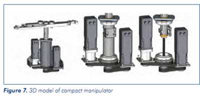
As already stressed, during the design of the new construction, attention was paid to minimising the number of components and the fact that these components should be produced as simply as possible. On the basis of theserequirements, a new “two-tube” concept of manipulator was created. Its aim is not only to minimise the number of components representing the manipulator and to simplify their manufacturing, but it tries to achieve the maximum possible force relations in the mechanism of the manipulator and to eliminate excessive force originating from the improper arrangement of elements, constructions and/or selection of material.
3.3 Compact manipulator THK
On the basis of the solution of the construction of the compact manipulator and, at the same time, in an effort to simplify the construction, an alternative for the inside mechanism of the manipulator was found in the form of acomponent offered by THK. It concerns the grooved bolt.
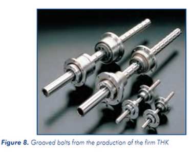
By implementing a special element which integrates a pair of properties, i.e. properties of the ball bolt and ball bar with grooves, it is possible to achieve similar properties to the above-mentioned properties. The whole process of change is achieved using two rotary movements. Primarily this element is designated for implementation into the robots of Scara type [Kolibal 1993], where the translation movement is implemented in the axis Z. From theviewpoint of functionality, robust character and compactness, it is also possible to apply this component with success in ATC manipulators. If we compare the above-mentioned concepts, it is possible to say that both variants have advantages and disadvantages. The firm has sufficient technology and capacity and it would prefer the variant for which it will try to minimise the price with the help of the production of components by cooperation, whereas, firmswithout the necessary technology or insufficient capacity would be likely to select ways which would necessitate the purchase of the maximum possible number of components.
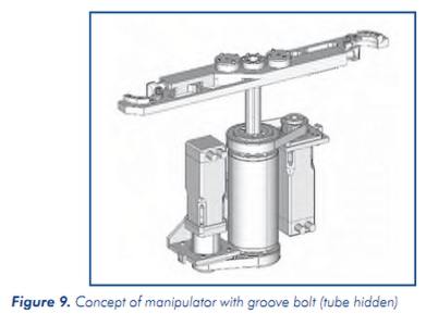
The advantages of the second variant are mainly in the completely rolling bedding which minimizes losses, its small built dimensions and also the simplicity of the solution which is based on one integrated purchased element. This also brings a great disadvantage, depending on a single or restricted number of suppliers able to deliver this component. A further disadvantage to mention is the necessary greater distance of the lower part of the manipulator from the other components. During the insertion of arms, there is pulling out of the bolt from the manipulator.
4. Impact activities in the case of blocking of the tool
During the implementation of experimental tests on the stand STD-25, an interesting action was noted concerning an issue related to the force effect of the arm of the manipulator on the tool or the spindle. More exactly, on thebasis of observation, it was seen that the arm of the conventional construction (blocking type with arresting thumb) generates a large impact during the clamping of the tool which may possibly damage bearing groups of the spindle. The blocking of the tool by the arm and overcoming of the resistance of the thumb also uses the kinetic energy of the moving parts of the manipulator. This important knowledge results from it. To be able to use the energy necessary for exceeding the force of the arresting thumb, it is necessary that, at the moment of the contact of the tool and the thumb, the arm has sufficient speed and energy.
With the aim of checking this action and the value of the originated impact force, an experiment was prepared and simulations were performed to try to quantify the value of the impact force. On the basis of implemented simulations, the maximum contact force 6300N was stated which acts on the tool and as a result also on the spindle. The value of this force cannot be easily ascertained, therefore, modal analysis equipment was used for itsidentification during experiments, i.e. accelerometer and modal hammer.
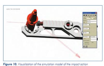
Experiments were performed that corresponded as far as possible to the real status of the machine. Two pairs of sets of measurements were performed. The first recorded with the use of accelerometer located on the stand impacts called by the manipulator – arm clamping the tool and the second series called excitation by means of the impact hammer. Everything was recorded by means of measuring apparatus and saved for further processing.
During measurement the precondition was used that the value of the response of the system was directly proportional to the value of the excited force, or the impulse of the force which was affected on this system. This verysimplified precondition can be performed on the basis of the fact that a hammer with metal pin was used for excitation, meaning contact metal – metal, in a similar way as for the real equipment. So, it is possible to suppose very similar times of effect of maximum force.
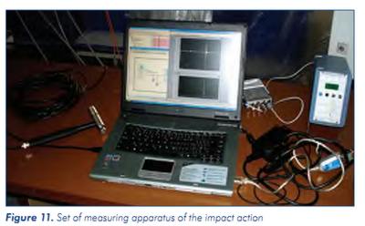
The value of the force der ived on the basis of measurement of responses of the system on the excitation of impact hammer and the arm of the manipulator was the force 7006N (see Tab. 2). If we compare this value with the calculated force 6300N, it is possible to state good compliance. For the verification of real force, it would be necessary to perform several further modifications on STD-25 and to use further sensor equipment to verify the value of the real force. As mentioned above, for the purpose of approximate specification of the value of force, this method is sufficient.
Despite the fact that this concerns forces which for most machines exceeded the permitted loading of the spindle, in this case, it is necessary to take increased care mainly about the fact that the spindle has always the same oriented rings of bearings, which means the cyclic stressing of one place on the inside and the outside ring of the bearing. Further risk is based on the speed of starting of the effecting force where the maximum is achieved during a very short period (fractions ms). It is necessary to point out that this issue concerns mainly machines equipped with very fast automatic tool change. In relation to the fact that the measurementwas performed at relatively long times of change of about 5s, it isnecessary to point out that ATC equipment with speeds of about 2s will effect a significantly higher force on the spindle which shouldbe taken into consideration.

It shows that an interesting area for further development is not only solutions based on the use of servo drives which enable fluent control of the route which can optimally restrict force effects on the spindle, but it is alsorecommended to focus on the area of the development of a system of clamping and arresting of tools in the arm which by their construction prevent the origination of these forces.
5. Conclusions
The work widely supports research performed within resolution of the project which aims to select the suitable market segment for machine tools for which it is possible to suppose potential for the application of new concepts. As potentially suitable, it mainly considers the area of small and medium-sized milling centres where at present the monopoly is in hands of Asian suppliers of unified equipment for the automatic tool change. The work submits a proposal for alternative solutions of manipulators for the replacement of tools towards the current mass delivery of cam mechanisms. With the use of modern methods, such as system analysis, 3D modelling, FEM calculations (strength, kinematics and dynamism) etc., construction designs of several alternative solutions of manipulators were created. For selected variants, simulation methods were developed for prediction of properties and behaviour of mechanisms.
In relation to the resolved project 1.2.4, it was financially possible to produce a pair of physical outputs – stands which served for verification of functional properties, as well as for the verification of simulation models which were produced with the help of SW MSC. ADAMS. A further important output resulting from the solution of the project and the cooperation of the team of the Brno workplace RCMT was the issue of a utility sample in 2010 for solution of single-cam manipulator for automatic tool change. At the same time, a patent proceeding was commenced, which is currently in progress.
The work attempts to submit construction proposals of possible variants of the solution of manipulators ATC which by their conception, as well as the construction and parameters, fulfil the strictest requirements of modern industry. The question only remains as to whether they will be put to their practical use or not.
Acknowledgements
These results were achieved with the financial contribution of the Ministry of Education, Youth and Sports within the project of research and development 1M0507.
References
1.Housa, J. and collective Construction numerically controlled machine tools (in Czech), Prague: SNTL, 1985. 287 s
2.Janicek, P. System approach to selected branches for technicians: Searching for coherences. First Brno. (in Czech) Brno: CERM Brno, 2007. ISBN 978-80-7204-554-9.
3.Kolibal, Z. Industrial robots I – Construction of industrial robots and manipulators (in Czech), Brno: BUT publisher in Brno, 1993. ISBN 80-214-0526-0
4.Marek, J. Design of CNC machine tools, Prague: MM publishing, s. r. o., 2006. ISBN 1212-2572
5.Poppeova, V. and collective Automation of engineering, 1st ed in Zilina (in Slovak): EDIS, 2002. 229 s. ISBN: 80-8070-009-5