MODELLING AND SIMULATION OF PROCESS: MACHINE INTERACTION IN GRINDING
Автор:Aurich, J.C.
Источник: Aurich, J.C. Modelling and simulation of process: machine interaction in grinding / J.C. Aurich, D. Biermann, H. Blum and oth. // Production Engineering. – 2009, Vol. 3. – P. 111-120.
Process models
A process model for grinding describes the complex relationship between process and machine parameters, and work results. The interaction is modelled by prediction of grinding forces, temperatures, grinding energies, surface integrity etc., depending on the process. Multiple approaches for building up a process model are presented in [1]. These include fundamental approaches as well as kinematic models, finite element method (FEM), molecular dynamics, physical and empirical, artificial neural nets, and rule based models.
This chapter focuses on the prediction of process forces occurring during grinding as an input value for a machine model in order to describe the interaction between the process and the machine structure. Due to the large number of abrasive grains with an unknown geometry which varies with time, grinding is a complex material removal operation [3].
The large number of input variables complicates the development of a universal model [4]. Due to different contact conditions, several models have been developed accounting for different grinding operations.
Kinematic-geometrical simulations are the basis of the presented process models. Therefore, the penetration between grinding wheel and workpiece is considered. Furthermore, these simulations can be distinguished between microscopic and macroscopic approaches which are described below. Their complexity and accuracy depend on the chosen modelling approach and the grinding process kinematics [1].
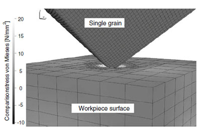
Fig. 1 Stresses in workpiece surface simulated by FEM [5]
Microscopic approaches
In microscopic approaches, the components participating in material machining are described in detail. In one approach, the grinding wheel consists of a detailed description of the complex 3D shape of each single grain and its randomly distributed position and orientation on the wheel, based on statistic functions determined by detailed statistical analyses of grinding wheel topographies [2]. Other approaches measure the wheel’s topography and use this data for detailed modelling.
A different microscopic approach is shown in Fig. 1. A 3D FEM simulation model, showing the occurring stresses during a single grain penetration, is used. The simulation can be extended by considering multiple statistically distributed grains to represent grains on certain paths. The computed stresses of the grains are used to calculate the process forces.
Based on the knowledge of the grinding wheel topography in combination with the process kinematics it is possible to simulate the machined material by each grain using a 3D FEM.
Another approach is presented in Fig. 2a. It shows an ideal penetration of single grains and the workpiece surface based on the process kinematic and the assumption of ideal chip formation. Possible parameters to characterise the undeformed chips of a single grain penetration are shown in Fig. 2b. Single grains are modelled by ideal octahedrons, cuboids, tetrahedrons and ellipsoids, randomized by additional planes in different orientations to generate a complex shape [6].
The knowledge of the machined material and the accumulated chip cross sections leads to a calculation of occurring forces using a Kienzle equation [7], which is adapted for grinding processes. Due to the permanently changing contact conditions, especially during NC-shape grinding and tool grinding processes, the allocation of the effective grinding force can be included.
Some experimentally determined and simulated forces with the associated resulting surfaces are shown in Fig. 3. The experimentally determined process specific grinding force kc,sim relates the chip cross section to the grinding forces. The simulation leads to a good approximation of occurring forces. Taking different grinding wheel topographies, i.e. grain distribution and grain size, into account, a prediction of the workpiece surface can be accomplished.
Macroscopic approaches
Macroscopic approaches describe the penetration of the workpiece by the shape of the grinding wheel without detailed specifications of the wheel’s topography. Figure 4 shows a 2D approach to calculate the machined material using the chip longitudinal section depending on the cutting depth, the workpiece velocity, the chosen time step and the position of the grinding wheel. Thus the currently machined material is taken into consideration which is important for processes with rapidly changing grinding forces, e.g. during run-in or run-out phase in pendulum and speed stroke grinding.
Based on an empirical grinding force model, the process forces can also be determined using a 3D kinematic-geometrical simulation [10]. An adapted Kienzle equation relates the machined material to the occurring forces. Therefore, a factor for the specific grinding force ratio is necessary, which has to be evaluated by empirical data. The empirical data is generated by experiments taking material properties and tribology effects into account. In the kinematic-geometrical simulation, the workpiece surfaces can be described by dexel models. A dexel model is applied on a NC-shape grinding process in [11, 12]. Thereby, a local distribution of the contact stresses can be calculated by a macroscopic FEM simulation.