Introduction
- Introduction
- 1. Relevance of the topic
- 2. The purpose and objectives of the study, the planned results
- 3. Description of system elements
- 3.1 Energy sources
- 3.2 Energy storage
- 4. Calculation of AC consumers
- 5. Development of energy management system
- Conclusions
- List of sources
Introduction
Autonomous power supply systems are systems that provide power to areas that are unable to take this electricity from nearby power stations. In such systems, both traditional and renewable energy sources can act as sources of electrical energy. Combined autonomous systems based on renewable energy sources such as wind and solar are considered the most promising. The main problems of such systems are associated with the necessity of efficient energy storage, taking into account the uneven supply of wind and solar energy and changes in the efficiency of its re-organization during the day and year.
1 Relevance of the topic
In recent years, there has been a trend of transition from traditional energy sources to renewable. To implement this transition, it is necessary to develop the theory and practice of using stand-alone systems. The object of research of this work is the autonomous power supply system of the site, based on different types of alternative energy sources. Also considered are the elements of this system and methods of its management.
Recent studies in the field of stand-alone systems demonstrate a tendency of transition from systems with one energy source (wind generator or solar battery) to hybrid systems using several energy sources at once. This reduces the number of batteries by 2 times due to the balancing nature of solar and wind energy intake throughout the year. In combined installations, an additional reserve energy source, hydrogen, is equipped, which allows reducing the number of batteries by a factor of 2 [1]. Energy management systems that use intelligent control algorithms become relevant, which makes it possible to rationalize the energy consumption policy and predict its generation [2].
2 The purpose and objectives of the study, the planned results
Goals and objectives of the study:
- Analysis and description of the general installation scheme;
- Description of the elements of the combined stand-alone system;
- A description of the energy management algorithm taking into account the weather forecast;
3 Description of system elements
3.1 Energy sources
The energy generated by the wind turbine and the solar battery, as well as the energy accumulated in the hydrogen plant, flows through a hybrid charge controller to the battery. Hydrogen installation is the accumulator of electric energy and the reserve power source. The system of energy management, depending on the level of charge of the battery, gives permission to turn on consumers of 1–4 groups. All energy consumers in this system were divided by priority of power and work. Consumers of the first group manage and monitor the operation of the system. They work around the clock. The first group of consumers includes: a charger, an inverter, a DC converter, a microcontroller, a control system, etc. The second group includes lighting, a laptop, a refrigerator, a satellite dish, a clock radio, a printer, a blender and a TV/DVD system. They have a low power rating (up to 300 W). Lighting and a refrigerator are used constantly, and a laptop is a means of communication. The third group of consumers includes a mini-washing machine (13l.) And a vacuum cleaner. Rated power of the 3rd group up to 700 watts. The fourth group of consumers includes powerful appliances from 1000 to 2200 W and above, such as an electric kettle, electric stove, boiler, iron. For a rational distribution of energy, a solution was proposed to avoid the simultaneous operation of several fourth group consumers. That is, simultaneous operation of consumers of the first three groups with only one device of the 4th group is possible. The weather forecasting unit transmits information on probable energy received in the future to the energy management system. This unit can be implemented through meteorological stations, data from which are taken from the Internet. The battery pack itself as part of the power supply system is operated in two modes: buffer and cyclic charge-discharge [3]. The power supply to the consumers is provided by an autonomous inverter connected to the battery
Figure 1 shows the block diagram of the combined installation.

Fig. 1 – Block diagram of an autonomous combined installation
The main sources of energy for an autonomous power station are a wind generator and a solar battery. For autonomous installations of low power (up to 10 kW), it is recommended to use wind generators with a vertical axis of rotation (Savonius rotor, Masgrove rotor, Darrieus rotor). They have several advantages [3]:
- Do not require orientation in the direction of the wind
- Work in any direction of the air flow
- Do not require a gear
- Low aerodynamic and infrasonic noise
- Small TV and Radio Interferences
- Low initial wind speed to get started (1 m / s)
Figure 2 shows the main types of wind turbines with a vertical axis of rotation.
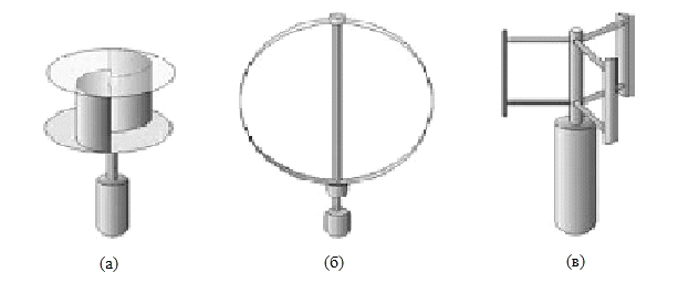
Fig. 2 – Types of wind turbines with a vertical axis: a – Savonius rotor, b – Darrieus rotor, c – Masgrov rotor (H-Darrieus)
Recently, the development of a combined type of a propeller Darrieus-Savonius. Due to the combination of two structures, this type of wind turbine has two indisputable advantages over classical types: first, this rotor has a high coefficient of rapidity due to the presence of Darrieus rotor blades, secondly, the presence of Savonius blades makes it possible to automatically start the installation, which Darrieus rotor initially lacked. [4,13]. This rotor is presented in Figures 3 and 4.
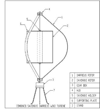
Fig. 3 – Diagram of the rotor Darrieus-Savonius

Fig. 4 – Darrieus-Savonius Combined Rotor
A solar cell is a semiconductor device that directly converts solar radiation into direct current. The most common solar cells are based on crystalline silicon. Figure 5 shows the operating principle of a solar panel. Silicon plates of photocells differ in manufacturing technology for single-crystal and polycrystalline. The former have a higher efficiency, but the cost of their production is higher [5].
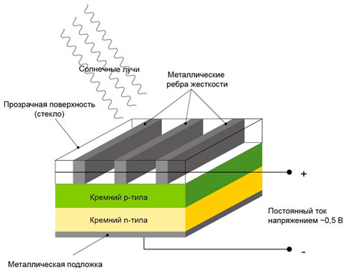
Fig. 5 – Structure and principle of operation of the solar battery
As can be seen from Figure 1, both the solar panel and the wind turbine are connected to the charge controller. Charge controllers convert electricity from wind generators and solar batteries into energy suitable for charging batteries, provide different charging currents to the battery, depending on the level of charge, and monitor the temperature inside the battery. Charge controllers are primarily needed to optimize and adjust the charge / discharge modes of the battery in order to extend their service life. Systematic overcharging leads to an increase in the cell temperature and subsequently exothermic reactions at the negative electrode, which leads to depressurization and ignition of the battery [6]. Deep discharge is dangerous for batteries because it leads to a decrease in battery capacity due to the dissolution of the solid electrolyte interface in the electrolyte. Recently, MPPT (Maximum Power Point Tracking) technology has been introduced in solar charge controllers, which makes it possible to obtain the highest possible output power thanks to DC switching converters [7]. The charge controller includes a control system implemented on the basis of a microcontroller and a power unit in the form of a pulse downconverter of direct voltage (buck converter), a simplified diagram of which is shown in Figure 6.

Fig. 6 – Typical impulse buck converter circuit
It is recommended to use charge controllers with a MPP tracking algorithm to get the most power from solar panels. There are 2 main algorithms for tracking TMM: perturbation and observation (perturbation and observation) and increasing conductivity (incrementing conductance). Figure 7 illustrates flowcharts of TMM algorithms: disturbances and observations and increasing conductivity [8].
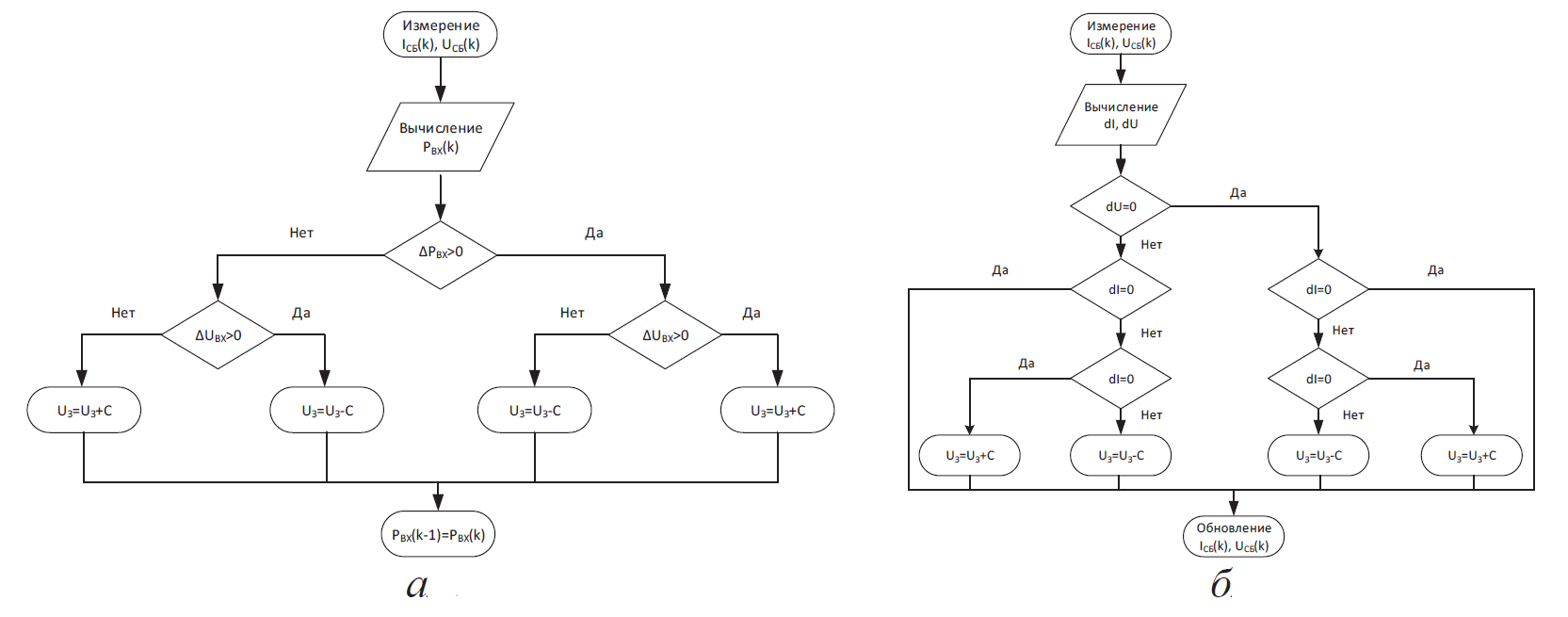
Fig. 7 – Flowcharts of algorithms for tracking the maximum power point by the method: a) disturbances and observations; b) increasing conductivity
A charge controller with a MPP tracking algorithm allows you to charge a battery with a nominal voltage lower than the rated voltage of the solar battery. That is, several series-connected solar modules with a voltage exceeding the rated voltage of the battery are connected to the input of the MPP controller (input voltage range, depending on the model, is 75-150 V). Also appeared charge controllers with a maximum input voltage up to 200V. Powerful charge controllers are designed for input current 60-80A (you can connect solar panels with a capacity of up to 4 kW at a system voltage of 48V).
When using the perturbation and observation method, the device changes the equivalent input resistance of the converter by a small amount (by varying the duty cycle of the power switch or changing the reference to the input values of voltage, current or power), resulting in varying voltage on the solar panel and then measuring its output parameters. If the power increases - the controller continues to change the setting parameter in the same direction, until the power stops increasing. This method is the most common, despite the fact that it leads to power fluctuations. The widespread use of this method due to its simplicity. In the incremental conductivity method, the converter detects an increase in the current and voltage of the solar battery to predict the effect of a voltage change. He trumpets the increase in computations with a microcontroller, but at the same time he tracks the hibernation of surrounding conditions with a greater speed than the method of perturbation and observation. This method also leads to power fluctuations. The method in question uses the increasing conductivity 24dI/24dU of the solar cell to calculate the sign of the power change with respect to the voltage 24dP/dU. This calculates the maximum power point and compares the increasing conductivity with the conductivity of the solar battery I/U. When the condition I/U=I/U is met, the output voltage is equal to the voltage corresponding to the highest power value. The considered algorithms are aimed primarily at finding the local maxima of the solar battery power. All of them involve power fluctuations that can be reduced by introducing step change algorithms. The algorithm of increasing conductivity works out changes in illumination much faster, but for correct operation it is necessary to perform more arithmetic operations on each clock cycle of its operation. The disadvantages of this method also include high sensitivity to interference and pitch change [9].
3.2 Energy storage
Despite the presence of batteries, there may be situations where neither the solar panels nor the wind installation can provide enough electricity to supply consumers due to bad weather conditions. For such cases, it is advisable to introduce another energy storage device that will accumulate energy at a time when the battery is fully charged and there is no special load on the autonomous network, for example, at night. The most promising are storage tanks based on the hydrogen cycle, consisting of a water electrolyzer and hydrogen (or oxygen) batteries. Due to electricity from a solar panel and wind turbine, during periods of low energy consumption, hydrogen gas (or oxygen) can be produced as a result of water electrolysis. Accumulated in the form of H2(O2) energy can be converted using an electrochemical generator and given to the consumer. Charge the hydrogen installation is planned alternating current coming from the inverter. At the output, the hydrogen plant will produce a constant current to the charge controller [8].
The most expensive and the weakest
link in autonomous power plants is the battery. In terms of energy consumption, lithium-ion batteries (based on MnO2/Mn2O4 manganese oxide, nickel oxide NiO2, and cobalt oxide CoO2) are the best. In recent years, the use of lithium-polymer batteries is gaining momentum due to the possibility of obtaining very flexible forms of batteries [10]. The advantages of lithium-ion batteries are not only higher capacity, but also the ability to work with a large load current. In addition, unlike nickel metal hydride batteries, lithium-ion batteries lack a so-called memory effect. These batteries are usually connected in series and in parallel to provide the current and voltage needed by the consumer. However, the temperature regime of the battery may vary depending on their location at the place of storage. Because of this, there may be a variation in characteristics that significantly affects their lifespan. To minimize the spread of characteristics, power supply systems are created with intelligent algorithms and a cell balancing device [6]. Figure 8 shows the principle of operation and the structure of the lithium-ion battery.

Fig. 8 – The principle of operation and the structure of the lithium-ion battery
To balance the state of charge and voltage on individual batteries in the battery, special balancing devices are used. The block diagram of this device is shown in Figure 8. For each pair of series-connected batteries in the battery, charge transfer
blocks are included, which include two switching keys and a switched capacitor. The capacitor constantly switches between two batteries, thus delivering a charge from batteries with a higher charge to batteries with a lower charge, gradually leveling the charge on them. In addition, each such unit needs simple control of switching of power switches. Several charge transfer
units can be used for a series circuit of high-voltage AB batteries. Since B2 ... Bn-1 batteries share their charge transfer
unit with two adjacent batteries, the charge can travel from one end of the series circuit to the other. The disadvantage of this scheme is the need for a large period of time to transport the charge, in the event that the battery with the highest charge and the battery with the lowest charge are on different sides of the series battery circuit. In this case, the charge will travel
through each battery with a waste of time and efficiency [11]. Figure 9 shows a diagram of balancing battery cells with one switched capacitor.

Fig. 9 – Structural control circuit of balancing with one switched capacitor for each pair of batteries
4 Calculation of AC consumers
In this paper, an autonomous combined installation is considered, which has no connection to the network, due to which it is the ideal solution to the problem of power supply to decentralized facilities. Autonomous combined systems can be both stationary and mobile. In stationary installations the power range varies from 1 to 4.6 kW, in mobile from 7 to 10 kW. The described stationary autonomous combined installation is designed for a power of 3 kW and has a lithium-ion rechargeable battery of 24 V. The calculation is performed taking into account the condition that the battery must provide uninterrupted power to AC consumers for 7 days without recharging. The load is determined by the power and operating time for a period of 7 days.
All energy consumers in this system were divided by priority of power and work. Consumers of the first group manage and monitor the operation of the system. They work around the clock. The first group of consumers includes: a charger, an inverter, a DC converter, a microcontroller, a control system, etc. The second group includes lighting, a laptop, a refrigerator, a satellite dish, a clock radio, a printer, a blender and a TV / DVD system. They have a low power rating (up to 300 W). Lighting and a refrigerator are used constantly, and a laptop is a means of communication. The third group of consumers includes a mini-washing machine (13l.) And a vacuum cleaner. Rated power of the 3rd group up to 700 watts. The fourth group of consumers includes powerful appliances from 1000 to 2200 W and above, such as an electric kettle, electric stove, boiler, iron. For a rational distribution of energy, a solution was proposed to avoid the simultaneous operation of several fourth group consumers. That is, simultaneous operation of consumers of the first three groups with only one device of the 4th group is possible.
Table 1 – AC consumers

5 Development of energy management system
The management of the combined autonomous installation is responsible for the energy management system. Its purpose is to determine the current level of accumulated energy and calculate the predicted energy, as well as to turn off or turn on certain groups of consumers due to an algorithm that estimates whether it will be rationally reduced or increased consumed power under the condition of future electricity replacement [12]. Figure 10 shows the algorithm of the energy management system.
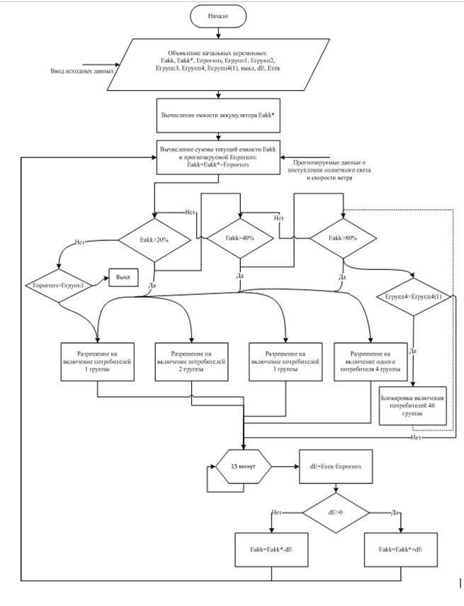
Fig. 10 – Block diagram of the energy management system management system
At the beginning, the control system algorithm declares the initial variables such as: Eakk, Eakk* – battery capacity, Epred – predicted power, which will be collected in 15 minutes, Egroup1–4 – power of 1–4 consumer groups. Egroup4(1) – the allowed power for consumers of the 4th group (the power of the most powerful device of the 4th group), off – the command to turn off, dE – the error value, Ecurrent – the current power value. After the variables are declared, the battery capacity Eakk* and the sum of the current and predicted Eakk are calculated. To calculate the predicted power, you need data from weather stations that can be obtained from the Internet, as well as data from many years of weather observations in the area of the site. After that, the control system asks for information about the battery charge and, depending on this, allows the inclusion of:
- If the energy is more than 20%, then the inclusion of 1 and 2 groups of consumers is allowed. If less then:
- If the future predicted capacity is capable of covering the power of 1 group, then there is permission to enable 1 group.
- If the predicted power is not enough, then there is a command to turn off.
- If the energy is more than 40%, then inclusion of 1, 2 and 3 consumer groups is allowed, if less – a comparison is made with 20%.
- If the energy is more than 80%, then inclusion of 1, 2, 3 groups and one consumer of group 4 is allowed, if it is less, comparison with 40% is allowed.
fter these conditions, after 15 minutes, the error dE is calculated, which is added or subtracted from Eakk and the algorithm is repeated. Also, the condition is realized under which, if the power consumption of 4 groups is greater than the allowable Egroup4(1), then all consumers of 4 groups are disconnected and the capacity comparison is returned to the condition.
Conclusions
As part of the research conducted, the use of a combined autonomous system using the energy of the sun, wind and hydrogen components is justified, which makes it possible to significantly reduce the required battery capacity. To optimize the operation of an autonomous installation, it is advisable to use energy management systems taking into account the weather forecast. Also, the calculation of the power consumers of alternating current necessary for the functioning of the area was carried out.
List of sources
- Лаошвили, Д. П. Разработка смешанной автономной энергосистемы на базе возобновляемых источников энергии / Д. П. Лаошвили, Г. К. Кохреидзе // Известия высших учебных заведений и энергетических объединений СНГ – Энергетика : научно-технический и производственный журнал. – 2010. – №3. – С. 10–15.
- В.И. Калашников Автономные микрогрид-системы с возобновляемыми источниками энергии, как элемент концепции smart grid. Перспективы развития / В.И Калашников, С.Н. Ткаченнко, П.А. Хижняк // ISSN 2079–3944. Вісник НТУ
ХПІ
, 2015. 12 (1121) - Коберси И.С. Разработка контроллера заряда-разряда для ветроэнергетических систем / И. С Коберси, Н.А. Фиров, Д.А. Сахно// Известия ЮФУ. Технические науки. – 2013. – № 2 С. 248–253
- Свободная энциклопедия Википедия, статья
Darrieus wind turbine
[Электронный ресурс] / Режим доступа: https://en.wikipedia.org - Принцип работы солнечной батареи: как устроена и работает солнечная панель [Электронный ресурс] / Режим доступа: http://sovet-ingenera.com
- Румянцев А.М. Поведение малогабаритных литий-ионных аккумуляторов в условиях перезаряда / А. М. Румянцев, Е. Г. Волжинская, В. В. Жданов. // Электрохимическая энергетика. 2007. – Т. 7 – № 2. – С. 73–77
- абина Л.В. Анализа ветроустановок для электростанций малой мощности // Научный журнал КубГАУ – №78(04) – 2012.
- Румянцев А.М. Поведение малогабаритных литий-ионных аккумуляторов в условиях перезаряда / А. М. Румянцев, Е. Г. Волжинская, В. В. Жданов. // Электрохимическая энергетика. 2007. – Т. 7 – № 2. – С. 73–77
- Русскин В.А. Исследование алгоритмов поиска точки максимальной мощности для повышающего преобразователя напряжения солнечного инвертора / В.А. Русскин, С.М. Семёнов, Р.К. Диксон // Известия Томского политехнического университета. Инжиниринг георесурсов. 2016. Т. 327. № 4. 78–87
- Свободная энциклопедия Википедия, статья
Литий-полимерный аккумулятор
[Электронный ресурс] / Режим доступа: https://ru.wikipedia.org - Cинь С. Математическая модель батареи литиево-ионных аккумуляторов // Выпускная квалификационная работа магистра. Санкт-Петербург 2016. с. 41
- Григораш О.В. Стабилизация напряжения автономных инверторов солнечных электростанций / О.В. Григораш, М.А Попучиева // Научный журнал КубГАУ – №130(06) – 2017.
- C. Srinivasan Design of Combined Savonius-Darrieus Wind Turbine / C.Srinivasan, G.Ajithkumar, S.Arul, G.Arulprasath, T.M.Dharunbabu // IOSR Journal of Mechanical and Civil Engineering (IOSR-JMCE) e–ISSN: 2278-1684,p-ISSN: 2320–334X, Volume 14, Issue 2 Ver. V (Mar.–Apr. 2017), PP 60–70
- Виссарионов В.И., Дерюгина Г.В., Кузнецова В.А., Малинин Н.К.,
Солнечная єнергетика
: Учебное пособие для вузов / Под ред. В.И.Виссарионова. – М.: Издательский дом МЭИ, 2008. – 320 с - Свободная энциклопедия Википедия, статья «Отслеживание точки максимальной мощности» [Электронный ресурс] / Режим доступа: https://en.wikipedia.org
