
Abstract
Содержание
- Introduction
- 1. Theme urgency
- 2. Purpose and objectives of the study, planned results
- 3. The main content of the work
- 3.1 Impact on power circuits grinding
- 3.2 The parameters of the cutting conditions
- References
Introduction
To non – rigid shafts are shafts in which the ratio of length to diameter more than 10. Non – rigid shafts are widely used in hydraulic cylinders drive feed machines, hydraulic lifts in aviation, construction, road and other machines. The accuracy of processing of such shafts corresponds to 6...8 quality, surface roughness Ra=0.63 ... 1.6 µm. Such indicators of accuracy and surface quality are usually achieved by grinding
Due to the low rigidity of these parts during their processing under the influence of the radial component of the cutting force, the bending of the workpiece axis occurs, whereby a barrel profile is formed instead of a cylindrical one – the diameters increase from the edges to the middle of the section. To obtain a given geometric accuracy in the processing of such parts must be carried out several passes, which leads to a decrease in processing performance. Therefore, the development of technological methods to ensure the geometric accuracy of non – rigid shafts in round grinding is an urgent scientific task of great practical importance.
1. Theme urgency
Ensuring geometric accuracy when grinding non – rigid shafts in mechanical engineering. As with other types of precision in grinding geometric accuracy is the key not only to eliminate the error of geometric shapes of surfaces (barrel, waviness, curvature of the axis, ovality , etc.), but is the key to improving productivity in engineering.
The master's work is devoted to the actual scientific problem of development to ensure geometric accuracy in grinding non – rigid shafts, aimed at increasing productivity in the workplace. As an experience,the part of the tiva "shaft"is used, and the research tools are Solid Works, grinding group machines, universal Assembly device ( UAD ) .
2. Purpose and objectives of the study, planned results
The purpose of the study is to determine the optimal cutting forces and stiffness of the technological system, providing less deformation of the workpiece by analyzing the theoretical and practical material
The main objectives of the study
- To consider the concept and essence in the grinding process of the required machining accuracy.
- To explore ways and scheme round outer grinding.
- To analyze ways to ensure geometric accuracy in grinding non – rigid shafts.
- Identify the causes of geometric accuracy is not when grinding non – rigid shafts.
- Choose the best way to solve this problem.
Research object: ensuring accuracy of shaft grinding.
Research subject: combination of the methods of reducing the hardware cost for implementation of roll grinding in production.
As part of the master's work it is planned to obtain relevant scientific result in following directions:
- The solution to the problem of ensuring geometric accuracy (cylindrical) of the part has two directions:
- 1) reduced cutting forces
- 2) increasing the rigidity of the technological system, providing less deformation of the workpiece.
For the experimental evaluation of the theoretical results and the formation of the Foundation for further research, as practical result it is planned to develop an optimal method for achieving accuracy in grinding the shaft with the following properties:
- The availability of the necessary literature.
- Availability of the necessary tools and equipment.
3. The main content of the work
The reason for the appearance of barrel in the processing of non – rigid shafts is the deflection of the workpiece under the influence of mainly radial component of the cutting force. The solution of the problem of ensuring geometric accuracy (cylindrical) of the part has two directions: 1) reduction of cutting forces; 2) increase of rigidity of the technological system that provides less deformation of the workpiece.
The second direction is solved mainly by the use of movable or fixed lunettes, which create additional support, reduce the deflection of the workpiece.
3.1 Impact on power circuits grinding
Reduction of cutting forces is solved in the following ways: when grinding, the same forces act as in other types of cutting processing, but their value is much smaller, since the cut dimensions are small, and cutting occurs at high speeds From the force scheme (Fig.1) it can be seen that the resultant R decomposes into three components: Pz, Py, Px and each of them is the sum of the elementary forces arising from the cutting of individual abrasive grains. The greatest radial force is Ra, it is 1.5...3 times more power PZ [1].
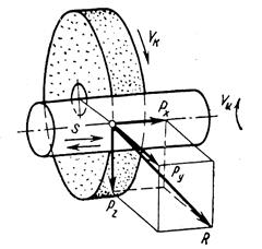
Figure 1 – cutting conditions in grinding
This is explained by the fact that the grains have a negative angle, and in such cases the RP increases greatly. Ru force should be as small as possible, as it causes the deflection of the part, deforms it, cauterizes. The reduction of the Ru is achieved by decreasing the speed Vu and the feeding Sn (t), timely straightening of the wheel. The magnitude of the force of Px is small and in the calculations it is not taken into account. It is experimentally established that the Pz force increases with increasing Vu, s, Sn and decreases with increasing Vk.
Grinding is carried out by abrasive wheels with abundant supply of coolant to the cutting zone and is the main method of finishing the outer surfaces. There are pre –, finishing and fine grinding. Pre – grinding provides accuracy of 8 – 9 quality. The surface roughness is 0.4 – 6.3 µm. Finishing grinding is carried out after heat treatment. They provide an accuracy of 6 – 7 quality with a surface roughness of 0.2 – 3.2 microns. Higher accuracy is achieved by fine grinding with a surface roughness of 0.025 – 0.1 µm. Grinding is divided into types: round and centerless.
Round grinding of the outer cylindrical and conical surfaces is performed on circular grinding machines and the part is installed in the centers, Chuck or collet. There are two main methods of round grinding: with longitudinal feed and method of cutting [2].

Figure 1 – cylindrical grinding: grinding with longitudinal feed (рис.2а),grinding by plunge – cut method (рис.2б), deep grinding (рис.2в).
Grinding with longitudinal feed is carried out by reciprocating movement of the part relative to the grinding wheel. For each double stroke of the table with a part of the circle moves to the center of the workpiece on 0,005 – 0,02 mm. grinding scheme with longitudinal feed is shown in the figure 2,а.
Grinding by cutting is made by a circle, the width of which is greater than the length of the treated area (рис. 2,б).In this case, the circle has only a cross feed. Simultaneous grinding of several surfaces by the method of cutting can be carried out shaped circle (рис. 2,в;). This method is more productive than grinding with longitudinal feed, so it is used in mass and large – scale production
Deep grinding (рис. 2,в) зin one pass remove a layer of material to the required depth. On a grinding wheel form a conical section with a length of 8 – 12 mm. during grinding, the conical section removes the main part of the cut layer, and the cylindrical section cleans the treated surface. No cross feed. Grinding wheels are characterized by the brand of abrasive material, grit, binder material, hardness, structure, shape, size, tool class and imbalance class [2].
Figure 3 – Deep grinding scheme(animation: 8 frames, 10 cycles of repetition, the size of the animation – 48 kbps)
3.2 The parameters of the cutting conditions
Grinding speed
The speed of rotation of the workpiece compared with the speed of the grinding wheel is very small, it is neglected and the grinding speed is called the speed of the grinding wheel.
The speed of rotation of the wheel is of great importance for the grinding process. The productivity of the grinding process increases with the speed of the wheel.
You need to choose the speed of the highest permissible values specified in GOST 4785 – 64 (depending on the shape of the circle, ligament, processed material, type of grinding, machine design).

Therefore, try to use the circle of the largest diameter, which can be installed on the machine, and choose the largest possible number of revolutions of the spindle. Limiting the speed of the circle is, as already mentioned, its strength and rigidity of the machine, tools, parts. At low rigidity of the system, high speeds lead to vibrations that reduce the accuracy, the class of roughness of the treated surface, increasing the wear of the circle.
Grinding depth (cross feed)
When rough grinding is advantageous to work with the greatest depth of cut (grinding), allowed the grain of the circle, the part and the machine. In this case, the cutting depth should not exceed five hundredths of the transverse grain size. So, for a circle with a grain size of 50 it should be less than 0,025 mm. at increase in depth of cutting of more admissible pores of a circle are quickly filled with a metal shaving and the circle is salted.
The depth of grinding should be reduced in the processing of non – rigid parts, loosely fixed to the machine, and the appearance of burns. When finishing grinding, the depth of grinding should be small, which increases the accuracy and class of roughness of processing.
Hard and durable materials are ground to a lower depth. With the increase of grinding depth increases the power required for friction and crushing of the chips.
Longitudinal feed
Longitudinal feed is measured in fractions of the width of the circle. For rough grinding it is 0.4 – 0.85 the width of the circle per revolution of the part. A larger feed value than 0.9 can not be taken, because with a larger feed on the surface of the grinding part will remain unpolished helical strip.
When finishing work longitudinal feed ranges from 0.2 to 0.4 of the width of the circle per revolution of the part. The more flow, the better the performance, but more surface roughness. The most rational cutting conditions (VC, VD, SPR) are selected according to the standards given in the manuals [5].
When determining the cutting conditions according to the standards, first determine the speed of the VD part (at the accepted speed of the circle, the size of the part), then the longitudinal feed of the SPR and the transverse st [8].
References
- Маталин А.А. Технология машиностроения / А.А. Маталин.– Л.:
Машиностроение
, Ленинград.отд – ние, 1985. – 496 с., ил. - ГМаслов Е.Н. Теория шлифования материалов / Е.Н. Маслов.– М.:
Машиностроение
, 1974. – 320 с. - Лурье Г.Б. Шлифование металлов / Г.Б. Лурье.– М.:
Машиностроение
, 1969.–172с. - Анурьев В.И. Справочник конструктора – машиностроителя: В 3 т. Т. 3. – 8 – е изд., перераб. и доп. Под ред. И.Н. Жестковой. – М.:
Машиностроение
, 2001. – 864 с. : ил. - Справочник технолога – машиностроителя. В 2 – х т. С74 Т. 1/Под ред. А.Г. Косиловой и Р.К. Мещерякова. – 4 – е изд., перераб. и доп. – М.:
Машиностроение
, 1986. 656 с., ил. - Космачёв И.Г. , Дугин В.Н., Немцев Б. А. Отделочные операции в машиностроении. – Л.: Лениздат, 1985. – 248 с. ил.
- Обработка металлов резанием: Справочник технолога А.А. Панов, В.В. Аникин, Н.Г. Бойм и др.; Под общ. ред. А.А. Панова. – М.:
Машиностроение
, 1988. – 736 с.: ил. - Справочник инструментальщика/ И.А. Ординарцев, Г.В. Филиппов, А.Н. Шевченко и др.; Под общ. ред. И.А. Ординарцева. Л.;
Машиностроение
. Ленинград отделение, 1987,–846 с.: ил..