
Abstract
Content
- Introduction
- 1. Analytical review
- 1.1 Stressed-deformed state in an asymmetric deformation zone
- 1.2 Changing rolling force in an asymmetric process
- 1.3 Purpose and objectives of the study
- 2. The method of studying the effect of asymmetric rolling on the energy-power parameters and strip thickness variation with kinematic asymmetry
- 2.1 Scheme of measurement of power parameters of rolling on a laboratory mill 100
- 2.2 Research Methods
- 2.3 Characteristics of laboratory equipment
- Conclusion
- References
Introduction
Growth in the production of steel plate is achieved by introducing new mills, increasing the mass of rolled initial ingots and slabs, increasing the reduction and rolling speed. Increasing the reduction during rolling of wide sheets leads to an increase in power loading of the roller nodes, increase in thickness and decrease in the flatness of the strips. The use of bending leads to additional loading of the working stands, the complexity of the design, weight gain, reduction in the use of power reserves of equipment. Thus, the power loading of the stands of sheet mills determines the energy consumption, the accuracy of the geometric dimensions of the product, the productivity of the mill, and the metal consumption per unit of finished product. The desire to reduce the rolling force, improve the accuracy of the finished sheet stimulates the search for new ways and methods to reduce energy consumption and the ability to influence the geometry of the sheets. Theoretical and experimental studies have shown that the reduction of energy-power parameters can be achieved as a result of applying the AP process.
A theoretical analysis of the AP was performed and studies of the speed and geometric asymmetry of the rolling process in a laboratory mill 100 are given. Statistical dependences of the effect of speed asymmetry on the plastic properties of rolled thick sheets are obtained. The simplified dependences used to determine the power loading of the cage. The dependences take into account the effect of the deformation parameters and the modulus of the rigidity of the stand on the absolute and relative change in the rolling forces under speed asymmetry.
1. Analytical review
1.1 Stressed-deformed state in an asymmetric deformation zone
The main provisions of the theory of longitudinal rolling is usually considered with the following assumptions:
- Uniform movement of the metal at its entrance and exit from the rolls in the steady state rolling process.
- Both work rolls are driven with the same torque load.
- The rolls have the same circumferential speeds and the same diameters.
- From both rolls side, the same friction coefficients.
- It is postulated that the mechanical properties of the rolled metal are uniform in thickness.
- The equality of the temperature of the roll in thickness is accepted.
Failure to comply with any of the above conditions results in symmetry breaking with respect to the horizontal rolling plane.
In an asymmetric process[1], the direction of the forces in the deformation zone and their values change, and this leads to a change in the deformation conditions on the drive and driven rolls.
In asymmetric rolling, when the peripheral speed of one roll (master) is greater than the speed of another (slave), there are three zones in the deformation zone Dн=246,4 Dв=251,36 [2]: the lead zone, the lag zone and the intermediate zone, where the friction forces on the drive and driven rolls are directed in opposite directions (Fig. 1).
The multidirectional forces of friction can be equated to the action of the front and rear tensions [3].
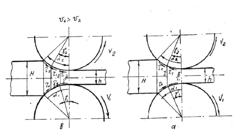
Figure 1 – The structure of the deformation zone: a - with symmetric rolling; b - with asymmetric.
According to V.G. Sinitsina [4], multidirectional friction forces can reach large values ??compared with the usual tension created by the winders and decoilers of reversible rolling mills. The author considers the process of asymmetric rolling of thin strips at ld/hср>2-2,5. For the analytical determination of energy-power parameters of asymmetric rolling, differential equilibrium equations are used [4].
Differential equilibrium equations are compiled for each zone of the deformation zone. Based on the theoretical analysis of the power parameters of symmetric and asymmetric rolling [4], it was found that the power parameters are lower with asymmetric rolling than with symmetric rolling.
The effect of reducing the power parameters of the process, due to the asymmetry of the process, increases with an increase in the intermediate zone.
The presence of an intermediate zone with different directions of friction forces leads to a change in the shape of the contact stress diagram. The dome-shaped top of the normal stress diagram is cut off. In the area where the friction forces are in the opposite direction, the normal contact stresses decrease as it approaches the exit from the deformation zone, that is, as the thickness decreases. The reduction of the normal contact stress in the deformation zone occurs before the complete advance zone on the drive roll.
1.2 Changing rolling force in an asymmetric process
The reduction in rolling force in the asymmetric process was confirmed in industrial, semi-industrial and laboratory conditions [4]. The laws of the effect of the asymmetric process on the rolling force during the rolling of thin strips, mainly from non-ferrous metals and alloys, have been most fully studied.
According to [4], the rolling force of annealed L63 brass in rolls of different diameters ld/hср>2-2,5 on the reversing mill 800 was 10-12% compared to conventional rolling, and moreover the higher the yield strength of the rolled metal, the higher the AP effect. Thus, during the rolling of copper M1i brass L90, the energy-power parameters decreased only by 5-10%, annealed brass L63- by 10-20%, and unannealed brass L63-by 20-30% with other things being equal.
The work [5] presents the results of a comparative experimental study in the production conditions of rolling thin sheets in a cold rolling mill with a two-roll and single-roll drive. It is shown that sheet-by-sheet rolling on mills with previously pressed rolls in the “bottom” is advisable to be carried out with one drive roller, using rolls of different diameters. When this occurs, the reduction of energy loading of the cage and drives.
1.3 Purpose and objectives of the study
From the above review we can draw the following conclusions:
- The presence of an additional middle zone, where the friction forces on the upper and lower rolls have the opposite direction, reduces the supporting effect on the rolling force, reduces the stress state of the metal and the stiffness of the roll during rolling.
- Controlling the length of the middle zone, it is possible to change the stiffness of the roll and, as a result, the rolling force, the elastic deformation of the cage and the roller system, and hence the thickness, transverse profile and flatness of the sheet.
- The AP process of thin bands with the ld/hср>2-2,5 has been studied most thoroughly..
- Experimental studies of speed asymmetry are mainly given under laboratory conditions.
- When rolling with an idle roll, the change in deformation forces is insignificant. In the generator mode of the drive of one of the rolls, the rolling force decreases by 6-17%. The greatest reduction in rolling forces is achieved using the PV process.
- Information about the energy and deformation parameters of the AP on CLW is very limited.
- In the literature, mainly, only the results of research without a description of the permanent technology and control devices for controlling and maintaining the asymmetry at a given level are given.
- Speed asymmetry by the mismatch of angular velocities is the most appropriate for regulating the geometry of sheets under CLW conditions.
2.Methodics of the study of the effect of asymmetric rolling on energy-power parameters and strip thickness variation with kinematic asymmetry
2.1 The scheme of measurement of power parameters of rolling on a laboratory mill 100
Figure 2 shows the measurement of power parameters.
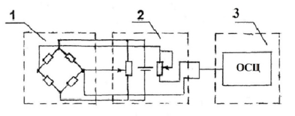
Figure 2 – Principle scheme for measuring the power parameters of the rolling process: 1 - strain gauge bridge; 2 - without reinforcement. block; 3 - oscilloscope H 145"
Under the pressure screws of the rolling mill, there are installed dozens, which are steel glass with glued KTD 2A sensors with acrylic glue. A bridge circuit was assembled from eight silicon sensors. One diagonal is powered by an unconditional block. The signal is removed from the other diagonal of the bridge and fed to the unconditional block. At the beginning of the measurement we conduct balancing of the bridge using instruments located in the unconditional block (micrometer with a midpoint). With an unconditional block, the signal is fed to a low frequency amplifier.
Calibration of the measuring circuit was performed using a DOSM 3-1 No. 621 dynamometer with the indicator ICh10MN.
The dynamometer works on the principle of determining the force from the magnitude of the elastic deformation of a special-shaped bracket.
The countdown of the load is done using an indicator and a table of load values ??that coincide with one or another indicator value entered in the graduation certificate.
The DOSM 3-1 dynamometer (Figure 3) consists of a bracket 1, which receives the load through the pillow 2, the ball 3, the upper stop 4 and the lower stop 5. The rack 6, which is fixed to the bracket with screws 7 and 8. On the rack 9 The indicator 10 is fastened. Under the influence of the load, the clamp is deformed and the lever 11, resting on the support 12, returns to the centers 14 and moves the indicator stem. Spring 13 is needed to exceed the friction in the conical centers 14.
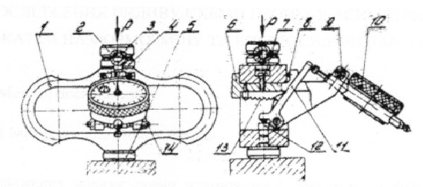
Figure 3 – General view of the dynamometer DOSM 3-1
2.2 Research methods
Studies of the effect of asymmetric rolling were carried out on a laboratory mill 100 with individual drive work rolls. Lead samples were used. The properties of lead rheology are similar to those of hot rolling steel.
2.3 Characteristics of laboratory equipment
Laboratory mill 100 is a single-mill “duo” mill (Fig.4). The main line includes: working stand, spindles, gear stand, radical coupling, gearbox, motor coupling, DC electric motor with a capacity of 3.6 kW, tachogenerator.
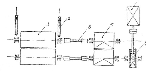
Figure 4 – The kinematic scheme of the rolling mill 100: 1 - rolls; 2 - pressure screws; 3 - rolling mill engine; 4 - worm gear; 5 - gear stand; 6 - spindles
Couplings on the spindle have a rectangular cross section. The working stand of the mill has two steel welded beds of the closed type, in which there are 4 pillows with sliding bearings. Spring roll trimming. Pressure device screw with a manual drive and a device for setting the size of the gap between the rollers. Separate operation of the right and left pressure screws is possible.
The upper roller is moved by means of two push-screws 2, connected through helical gears with a steering wheel. Balancing the upper roll - spring. The setting of the gap between the rollers is controlled using the hour scale of the pressure device, the division value of which is 3.6 mm (1 turn) and 0.3 mm (1/12 turn) hour hand respectively.
The rolls are driven by a DC electric motor 3 with a power of 3.6 kW and rotational speed, which is regulated through a worm gear 4 and a gear stand 5. The motor is powered from a rectifier assembled according to a bridge circuit. The engine is started from a separate DC source. The motor speed is adjustable from 0 to 30 rpm. Gear ratio i = 32. Rolling speed V = 0.02-0.16 m / s. The spindles 6 are used to transfer torque from the gear stand to the rolls. The mill is equipped with axial regulation of the mill rolls, which is carried out by means of towbars. Mesdoses or protective glasses are installed under the pressure screws of the mill, which prevent breakage of more expensive parts of the rolling stand. To facilitate the delivery of samples to the rolls, the mill is equipped with tables with sputtering fittings.
To create a difference in the rotational speeds of the rolls, the drive of the drive roll was made through the drive line of the mill 100, and the drive of the driven roll through the line of the mill 250. The spindle is shown in Figure 5, and the drive diagram in Figure 6.
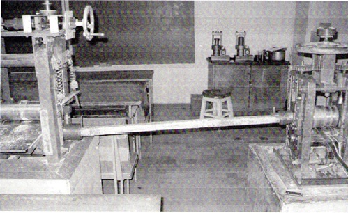
Figure 5 – Connection of roll drives for kinematic asymmetry
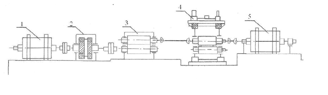
Figure 6 – The scheme of the mill for rolling with speed asymmetry: 1-engine mill "Duo"; 2- gear; 3-gear crate; 4- rolling stand; 5- Quarto Mill Engine
In the course of the work, we recorded energy-power parameters with symmetric and asymmetric rolling, given in table 1.
Table1 - Thickness and width of the sample after asymmetric rolling
| Pass number | Thickness Н, мм | Width on the top roll, мм | Rolling speed, об/мин | Rolling force, КН | ||
| On the top roll | On driven roll | With a symmetrical process | Asymmetric process | |||
| 0 | 30 | 40 | - | - | - | - |
| 1 | 28 | 41 | 8 | 5 | 45,4 | 44,5 |
| 2 | 27 | 42 | 8,3 | 5,1 | 50,8 | 49,5 |
Conclusion
The analysis of the literature data of existing rolling patterns with speed asymmetry is a hot topic.
As a result of the study of energy-power parameters, it was found that the use of kinematic asymmetry does not lead to exceeding the permissible values of the current and voltage of the driving motors, and the rolling force decreased by 5%.
The research results can be used when rolling on plate reversible mills.
References
- Целиков, А.И. Основы теории прокатки / А.И. Целиков. - М.: Металлургия, 1970.- 358 с.
- Целиков, А.И. Теория прокатки / А.И. Целиков, А.И. Гришков.- М.: Металлургия, 1970.- 358 с.
- Королев, А.А. Новые исследования деформации металла при прокатке/ А.А. Королев. - М.: Машгиз, 1953.- 268 с.
- Синицын, В.Т. Несимметричная прокатка листов и лент / В.Т. Синицын. - М.: Металлургия, 1984.- 167 с.
- Скороход, В.Н. Освоение холодной прокатки и дрессировки тонких полос с рассогласованием скоростей валков / В.Н. Скороход, Ю.В. Липухин, А.Ф. Пименов и др. // Сталь.- 1983. - № 8. С. 98-52.