
Abstract
Content
- Introduction
- 1. Relevance of the topic
- 2. The purpose and objectives of the study, expected results
- 3. Review of the literature
- 3.1 The pumps and their classification
- 3.2 Basic parameters of pumps
- 3.3 Structure, characteristics and scope of the centrifugal pump
- 3.4 The electric centrifugal pumps
- 4. Methods of connecting three-phase motor in the single-phase network
- 4.1 Capacitor start scheme
triangle
- 4.2 Capacitor start scheme
star
- List of sources
Introduction
Currently, the pumps are widely used, both at work and at home. There are several types of commonly used pumps. Volumetric and vortex pumps are more economical for high pressures and small flow rates, however they have elements of metal contact or friction pair, and that many important tight dimensional tolerances, it reduces the reliability, reduce the service life and hinders their use with viscous liquids . These pumps are complicated methods of regulating the pressure and flow [1]. Centrifugal pumps are more simple and reliable, they are much more likely to be found in various sectors of the economy and ordinary homes, this type of pump, I chose to study the in his master's thesis.
1. Relevance of the topic
The most effective indicators of pressure and flow are achieved by means of a three-phase power network, but not every business and even more so, not every average user at home have access to the network, so the problem of the three-phase electric power from a single-phase network is becoming increasingly important. There are various ways to connect this ED to a single phase: capacitor run circuits star, capacitor start delta, through the launch of an electronic key, run through a frequency converter and others. The simplest of them – is the use of schemes of the third contact connect through the phase-shifting capacitor. Gets an edge energy efficiency and cost-effectiveness of this method, the study of the power supply circuit will give an answer.
2. The purpose and objectives of the study, expected results
The purpose of the master work is to analyze the influence of power supply circuits for electric energy performance of the pump.
Research objectives:
- Review of the literature on the principle of operation, design, performance and power performance of centrifugal pumps;
- Review of the literature on the three-phase electric power through a single-phase network;
- Create a mathematical model and examine it for various methods of incorporating three-phase electric pump in a single-phase network;
- On the basis of studies to identify and analyze the most effective power scheme.
- Implement them in a pilot plant to confirm the adequacy of the mathematical model.
Expected outcomes:
- A mathematical model of the electric pump with the various switching circuits in the network;
- Physically implement various power supply circuit in a pilot plant;
- Formulate guidelines for choosing the connection method in three-phase electric pump on the basis of a single-phase network feed rates obtained experimentally and energy consumed.
3. Review of the literature
3.1 Pumps and their classification
For a long time it was customary to assume that pumps designed only for pumping water, but today their range of applications has increased so that this definition can not display the entire essence of the concept. Who is most to correctly identify the pump as a hydraulic machine, in which the mechanical energy produced by the engine is converted into the energy of the fluid [2].
Classify pumps made on the principle of action and design of the working chamber. They are divided into two main groups – the dynamic and three-dimensional [3].
Dynamic pumps – a pump in which the liquid moves under the influence of kinetic energy with the camera.
Positive displacement pumps – a mechanism in which the liquid moves under the influence of the potential energy due to changes in volume of the chamber with the liquid [4].
Dynamic, in turn, are divided by forces of mind, acting on a liquid medium:
- Volumetric pumps – in which fluid flow is moved by the blades;
- Electromagnetic pumps – designed to move the conductive fluid under the influence of the magnetic field;
- Pumps friction – in which fluid is moved by the action of frictional forces.
Positive displacement pumps are most often classified by the nature of the impeller motion:
- Vane pumps – hand pump in which liquid is displaced by means of the impeller;
- Rotary Pumps – fluid is pumped into them by means of a rotational or rotational-translational activities;
- Reciprocating pump – they are working parts make linear reciprocating motion, regardless of the nature of the motion of the driving member.
Dynamic and centrifugal pumps are in turn divided into axial and centrifugal.
In fact, in these types of pumps the liquid continuous flow is moved by interaction with the movable rotating rotor blades and the fixed blades body. However, in axial pumps fluid flows parallel to the rotor axis, i.e. in the axial direction, and a centrifugal – perpendicular, i.e. radially.
The most popular type of pump is a centrifugal pump. Due to its simple design, relatively low cost and reliability, it is used more frequently than others both at home and at work.
3.2 The main parameters of the pumps
The pump in accordance with the purpose characterized by three parameters: supply pressure and power.
Feed pump it represents the amount of fluid to be pumped to them per unit time. The amount of fluid supplied may be measured by volume or weight, depending on the nature of the pump.
For volumetric feed Qdimension is characterized by a unit volume in unit time, i.e. m3/h, m3/sec, l/min and so on, and for weighting feed G – unit weight in unit time, i.e., t/h, kg/sec, and the like. It becomes clear that the weight associated with bulk feed by the following formula:

where γ – specific weight of the liquid, N/m3.
Pump head H referred to increment the mechanical power received by each kilogram of liquid passing through the pump, i.e. the difference in specific energy of fluid at the outlet and inlet of the pump.
Specific energy flow at the outlet of the pump is calculated by the following formula:
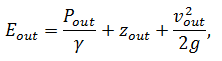
wherePout – flow pressure at the pump outlet, Pa;
zout – the height of the flow at the pump outlet, m;
vout – flow rate at the pump outlet, m/sec;
γ – specific weight of the liquid, N/m3;
g – acceleration due to gravity in m/sec2.
Similarly, one can calculate the specific energy at the pump inlet:
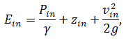
where Pin – flow pressure at the pump inlet, Pa;
zin – the height of the flow at the pump inlet, m;
vin – flow rate at the pump inlet, m/sec;
Thus, we derive the formula finding pressure:
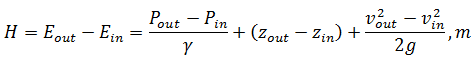
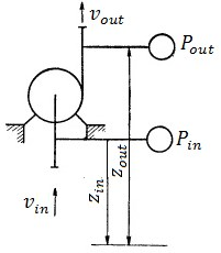
Figure 1 – Pump pressure measurement
The last and the main parameter characterizing the pump is consumed by their power N. In order to define it, first of all, it is necessary to give the concept of net power Nn, follow logically from concepts of head and flow. The increment of the energy of each kilogram of fluid delivered by the pump, the pressure is equal to H; amount of liquid, the transfer pump per unit time is equal to the weight applying G; in turn, the total increment of energy received over the flow of the pump per unit time and called the net power Nn [2]:
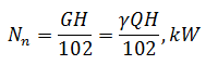
where H – pressure pump, m;
Q – volumetric pump flow, m3/sec;
G – weighting pump flow, kg/s;
γ – specific weight of the liquid, N/m3;
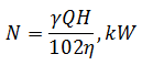
Further it is necessary to find the efficiency of the pump, is determined by the ratio of the net power Nn consumption to N:
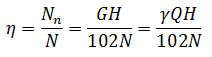
Consequently, the efficiency of finding the formula can determine power consumption:
3.3 The construction, characteristics and scope of the centrifugal pump
Centrifugal pump – a pump in which pressure and fluid movement occurs under the action of centrifugal force that occurs upon exposure of the impeller on the liquid [5].
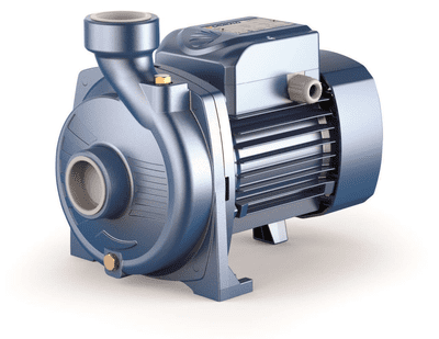
Figure 2 – A centrifugal pump
Inside the housing of the centrifugal pump is rigidly fixed to the shaft an impeller, which, in turn, consists of the front and rear discs between which are secured blades. They are bent from the radial direction to the opposite side of the wheel. Also, the pump housing is connected to the suction and discharge lines via nozzles.
When the pump body is completely filled with fluid from the suction nozzle, when the pump is turned on, i.e. imparting rotation shaft of the motor means, the liquid between the impeller vanes, It starts to drop from the wheel center to the periphery by centrifugal force. Thus, in the center of the impeller will create a vacuum, and the periphery of the opposite – the pressure will rise. Further pressure forces liquid into the pressure line. This will cause that the vacuum formed within the pump under the action of which the liquid will flow simultaneously from the suction conduit. Ultimately, there is a continuous supply of liquid from the suction port into the pressure [5].
Centrifugal pumps may also have more than one impeller (multistage centrifugal pumps), but the principle of operation will be the same – the liquid to be pumped by means of centrifugal force.
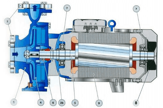
1 – pump body; 2 – flanges of the pipeline; 3 – the case of the electric motor; 4 – impeller; 5 – the motor shaft; 6 – shaft seal; 7 – Bearings; 8 – the impeller motor cooling; 9 – stator.
Figure 3 – The structure of the centrifugal pump [7]
Characteristic of the centrifugal pump, as well as any of the pump, called the relation of feed pressure Q-H at a constant number of revolutions n.The complete characterization also includes the curves of total efficiency and power.
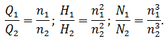
When changing speed curves Q-Hit changes so that the characteristic features of them are saved. Changing curves of head, flow and power at different rotational speeds obeys the similarity law. They were originally derived experimentally, but in the future a reliable theoretical basis was derived for them.

Figure 4 – The actual characteristics of the centrifugal pump
(animation: 6 frames, 7 repetition cycles, 40.6 kilobytes)
Scaling laws applicable to each point of the curve Q-H, they state that when the number of revolutions of supply will vary in proportion to the number of revolutions n, the pressure will change in proportion to the square of the number of revolutions n2, and power – in proportion to the cube of the number of turns n3. The latter assumption is based on what remains constant, when the number of revolutions efficiency.[8].
Scaling laws can be expressed as follows:
To date, it is practically impossible to find a branch or household industries, which would use liquid or applied centrifugal pumps. The most popular applications:
- Water supply of industrial enterprises and residential buildings;
- Pumping fluids in industrial plants and between them;
- Support for circulating coolant in central and local heating systems;
- Circulation of water in domestic appliances, such as washing or in dishwashers;
- Irrigation of agricultural plantations;
- Implementation of supplying water to the drinkers and pumping milk farm;
- The circulation of coolant in the climate systems and in automobile engine cooling system;
- Draining and filling the ballast tanks on submarines and surface boats;
- Transportation of materials in the food industry for mass production of beverages [9].
3.4 Motor centrifugal pumps
The drive systems for pumps supply AC motors. Its spread they received due to compactness, ease of connection to the pump, easy automation and the relatively low power consumption.
It drives pumps to meet a series of requirements such as the need for high capacity and starting the engine under load. Also the motor design should avoid prolonged rotation of the rotor in the opposite direction, which is caused by draining water from the pressure piping of the pump when disconnected from power.
A very important indicator for the pump Electric Drive is the ability to re-launches of short-term, which, in turn, places high demands on the construction start-up of the stator winding.
For small pumps used most often short-circuited asynchronous motors (Figure 5). They are much cheaper than other types of electric motors and much easier to maintain. When starting with squirrel-cage induction motor no additional devices, which considerably simplifies the automatic pump control circuit [10].
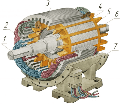
1 – the shaft; 2 – the stator windings; 3 – the stator core; 4 – cage rotor; 5 – rotor core; 6 – the fan impeller; 7 – housing.
Figure 5 – Structure of squirrel-cage induction motor
However, these engines have a significant drawback – a high multiplicity of inrush current during direct on, they exceed the rated current of 5-7 times. Such a short-term boost current is relatively safe for the engine, but it causes a sharp decrease in the voltage supply, which could adversely affect its other users, so the maximum permissible power with squirrel-cage induction motor for direct start relatively small – up to 100 kW.
4. Methods for connecting the three-phase motor in a single-phase network
People are often faced with a lack of network 380 V as at home, but that does not mean that they do not have the possibility to use three-phase pumps. Of course, it is necessary to sacrifice 30% of nameplate capacity, but for most purposes in everyday life is very acceptable.
The main problem of such a connection is creating a rotating magnetic field which induces EMFin a short-circuited rotor. To do this, you must move the phase windings at 120°, but in practice it is difficult to implement such schemes are rather expensive and their manufacture and setup require high qualifications. Therefore, in most cases, used simple and inexpensive circuitry, thus sacrificing some power. The phase shift using a capacitor – one of them.
When using this method a phase shift occurs only at 90°, but it is enough to appear on the rotor the required torque [11].
There are two main circuits connecting the phase-shifting capacitor – triangle
and star
.Typically, a run capacitor СR connected in parallel with one of the windings, as shown in Figure 6.
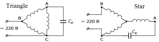
Figure 6 – Scheme connecting the condenser plates
4.1 Capacitor start scheme triangle
When capacitor startup circuit triangle
phase alternate connection start to the end of the previous one, wherein one of the phases
connected in parallel with the run capacitor. This starting method achieves a greater net power than start wye, but requires a large inrush current
surges, which could adversely affect the motor [12].
Calculation of the working capacity of the capacitor СR to connect the windings of the triangle is shown below:
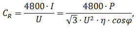
where I – current, A;
U – supply voltage, V;
P – power, W;
η – efficiency;
cosφ – power factor.
4.1 Capacitor start scheme star
When you start the motor on a star
" by the capacitor winding ends must be
collected on a single terminal - neutral, but its origins bring to the terminal block for
connection to the network. This starting method enables smooth start without strong inrush
current surges, but the net power engine will produce less [12].
In this case, the working capacity of the condenser will be calculated as follows:
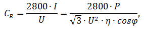
From the formula it can be seen that the capacitance of the capacitor when starting on
a star
less than running on a triangel
is approximately 1.7 times. From this
we can conclude that the condenser run scheme star
more economical, so if high power
is not required on the drive, it is recommended to use this scheme.
Список источников
- Спасский К. Н. Новые насосы для малых подач и высоких напоров / Спасский К. Н., Шаумян В. В. – М.: Машиностроение, 1972. – 160с.
- Ломакин А. А. Центробежные и осевые насосы / Ломакин А. А., Васильева В. П., Орлова Л. И. – Ленинградское отделение издательства «Машиностроение», 1966. – 358с.
- Насос. Электронный ресурс. Режим доступа: https://ru.wikipedia.org/...
- Виды и классификации насосов. Электронный ресурс. Режим доступа: https://proagregat.com/...
- Центробежный насос. Электронный ресурс. Режим доступа: https://dic.academic.ru/...
- Динамические насосы. Электронный ресурс. Режим доступа: https://rupumps.com/...
- Устройство центробежного насоса. Электронный ресурс. Режим доступа: http://www.ktto.com.ua/...
- Stepanoff A. J. Centrifugal and axial flow pumps / Stepanoff A. J. – New York. – 2nd Edition. – John Wiley & Sons, INc., 1960. – 430pp.
- Пневматика и гидравлика. Электронный ресурс. Режим доступа: https://stankiexpert.ru/...
- Электродвигатели для насосов и насосного оборудования. Электронный ресурс. Режим доступа: https://www.szemo.ru/...
- Как подключить трехфазный электродвигатель в сеть 220 В. Электронный ресурс. Режим доступа: https://stroyday.ru/...
- Трехфазный двигатель в однофазную сеть. Электронный ресурс. Режим доступа. Электронный ресурс. Режим доступа: https://zen.yandex.ru/...