
Abstract
Content
- Introduction
- 1. Relevance of the topic
- 2. Formalization of the control object
- 3. Review of research and developmen
- 4. Synthesis of an automatic pH control system
- 5. Analysis of the dynamics of ATS pH level
- Conclusion
- References
Introduction
Automation is one of the main areas of scientific and technological progress. Increasing labor productivity is achieved mainly by increasing the capacity of the units and their automation. The most important technological processes at TPP – PVS include processes for the production of chemically pure water used as a coolant. The chemical water treatment plant is a complex of powerful plants for pre–treatment and chemical desalination of water, which is used to compensate for the loss of coolant, for softening the water used in the heating system, and for cleaning condensate from turbines and condensate returned from production.
Automation of water treatment plants, in addition to reducing labor costs for maintenance and improving the reliability of the installation, gives a technical and economic effect by optimizing and intensifying the processes of technological processes and ensuring the production of water of guaranteed quality.
The transition to the higher stages of automation of chemical water treatment, including full automation, including chemical control and logical control with the help of control systems (ACS), does not give a significant reduction in personnel (due to an increase in the personnel of the instrumentation and automation department), but significantly increases the reliability of equipment operation at the same time increasing the technical level of automated equipment and can significantly intensify the operation of plants and improve the working conditions of personnel.
The aim of the work is to develop a system for automatic control of the pH level of water at the outlet of the clarifier.
1. Relevance of the topic
The TPP – PVS workshop (cogeneration plant – steam blow station) is located on the territory of the Donetsk Metallurgical Plant and is designed to provide consumers with process steam, heat, and electricity generation. In the winter (heating) period, TPP – PVS works according to the heat schedule, in summer – according to the electric schedule using excess blast furnace and coke oven gases.
TPP – PVS consists of the following workshops: a boiler shop, a machine shop, chemical water treatment, and an electric shop. The trouble–free and economical operation of the CHP equipment is largely determined by the complex of technological measures for water treatment.
Chemical water purification is intended for the preparation of water suitable for feeding boilers. Feed water is a mixture of turbine condensate and additional water supplied from chemical water treatment. In order not to precipitate in the pipes forming the heating surface of the boilers, the water should not contain salts [1]. To remove salts, additional water passes through a system of special filters installed in the chemical water treatment building, which is located on the territory of TPP – PVS.
Concentrated milk of lime is a suspension, therefore, in the cells, in order to avoid sedimentation of lime particles, air is supplied for constant mixing.
With metering pumps, the milk of lime is fed into the lower cone of the clarifier. Raw water is supplied there, preheated to a temperature of 35 ° C and passed through an air separator. Water rises to the top of the clarifier, where it enters the collection chute, and then through the collection pocket into the pipeline, through which it flows by gravity to mechanical filters. In the clarifier, the source water is treated with lime, resulting in partial softening of the water, reduction of organic matter and iron. The method is based on the binding of ions to be removed into sparingly soluble compounds deposited in the form of sludge, which is then removed from the treated water [2].
The lime water after clarifiers is fed into a common collector, from where it enters the mechanical two–chamber filters.
Figure 1 – TP for chemical treatment of water (animation: 10 frames, 10 cycles of repetition, 45 kilobytes)
2. Formalization of the control object
The technological scheme of chemical water treatment in the conditions of TPP – PVS of the Donetsk Metallurgical Plant is carried out by the reagent method. This method is most widely used to neutralize acidic wastewater. Material and information flows of the process are presented in Fig. 2.
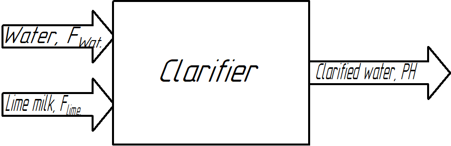
Figure 2 – Scheme of material and information flows
Since metal ions are almost always present in acidic and alkaline industrial wastewater, the dose of the reagent is determined taking into account the precipitation of heavy metal salts. Slurry Ca(OH)2 and quicklime CaO lime are used as reagents . Lime for neutralization is used in the form of lime milk of 5% concentration. The contact time of wastewater and reagent for acidic wastewater containing dissolved heavy metal ions should be at least 15 minutes [3].
In figure 3, the clarifier is considered as a control object.
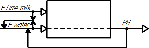
Figure 3 – Representation of the clarifier as a control object
The output parameters of the clarifier are the pH level of the water at the outlet of the clarifier, which must be maintained at a certain value to maintain the quality of chemically purified water.
The leading unregulated flow is the flow of lime milk, and the controlled driven flow is the flow of raw water.
3. Review of research and development
At the moment, the most common deviation control systems based on industrial regulators such as PID and its variations (Fig. 4).
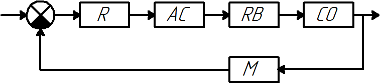
Figure 4 – Deviation control system
R – regulator of the pH level of water in the clarifier;
AC – actuator, the engine turns the flap of the feed water;
RB – regulatory body, water supply flap;
CO – control object (clarifier);
M – measurement of the pH level of water at the outlet of the clarifier.
In closed ATS control action is formed in direct dependence on the controlled value. In a closed system, the signal from the output of the sensor D, measuring the output value, is fed to the input of the system.
Continuous PI – or PID – regulators have proven themselves well for regulating neutralization processes. To ensure stable pH control, special systems with two control valves are used. Coarse control valve with large nominal diameter is set to the maximum range of the regulator output signal. And the valve, which serves for precise control, is designed for lower throughput and tuned for slight deviations of the pH level from the set value. Thus, with a slight deviation in pH, the regulation is carried out by the valve of the internal circuit, if the deviations exceed the specified error, then the valve of the external circuit with a larger flow rate.
4. Synthesis of an automatic pH control system
A common feature of pH regulation is the non–linearity of their static characteristics [4], associated with the non–linear dependence of pH on the consumption of reagents. Figure 5 shows a titration curve characterizing the dependence of pH on reagent consumption.
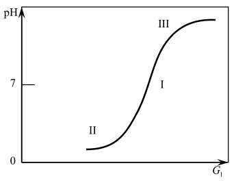
Figure 5 – The dependence of pH on the consumption of reagent
From Fig. 5 it follows that the range of changes in pH is from 3 ... 14 units. For various given pH values on this curve, three characteristic sections can be distinguished: the first (middle), which relates to almost neutral media, is close to linear and is characterized by a large gain. The second and third sections, refer to h2ly alkaline or acidic environments, have the greatest curvature.
In the conditions of the technological scheme of purification of source water, considered in bachelor's work, neutralization is carried out by a reagent method. This method is most widely used to neutralize acidic waters.
Since metal ions are almost always present in acidic and alkaline industrial wastewater, the dose of the reagent is determined taking into account the precipitation of heavy metal salts. Slurry Ca(OH)2 and quicklime CaO lime are used as reagents . Lime for neutralization is used in the form of lime milk of 5% concentration. The contact time of wastewater and reagent for acidic wastewater containing dissolved heavy metal ions should be at least 15 minutes [5].
Based on the requirements for pH = 11 units, we can conclude that during cleaning they tend to make water more alkaline. Analyzing the figure, we can conclude that the working point in the region of which the neutralization process can be formalized is closer to the third section, but still in the linear zone. This circumstance will allow us to accurately describe the process of neutralization by a differential equation of the first order with delay [6–7].
When analyzing the technological scheme of purification, it was found that the supply of the reagent (milk of lime) is supplied by the DIMBA–40 dispenser with a constant capacity of 40 m3/h [6]. The flow rate of the source water, which must be neutralized, is 250 m3/hour.
When developing the concept of ATS pH level, it was found that the control action is the flow of source water. Therefore, the mathematical model of the control object can be represented as a transfer function along the control channel pH level – flow rate of the source water
with a delay:
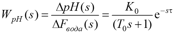
where  , T0 = 100 s; τ = 40 s. The choice of the object time constant is determined by the contact time of wastewater and a reagent for acidic wastewater, which should be at least 15 minutes.
The simulation scheme of the opamp is shown in Fig. 6. In the diagram, the level is limited by real technologically possible data of 3 to 14 units.
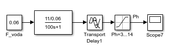
Figure 6 – Scheme of modeling the OS by channel pH level - feed water flow
The transient response of the pH level is shown in Fig. 7. The time of the transient process of the OS is about 10 minutes, a smooth aperiodic process without overshoot. Thus, the model adequately reflects the dynamics and is consistent. This model of OS will be the base when building the ATS pH level.
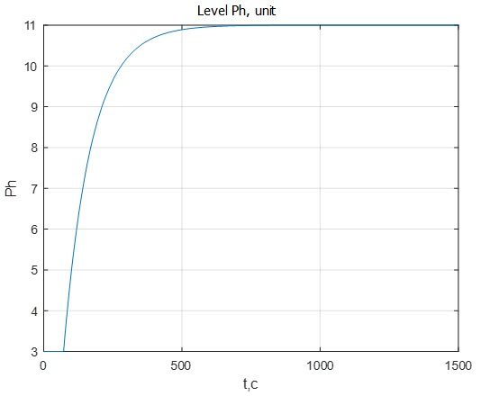
Figure 7 – Transient response of the pH level
5. Analysis of the dynamics of ATS pH level
The transient response of the pH level is shown in Fig. 8. The graph depicts not only the transient pH process, but also the signal of the setting action.
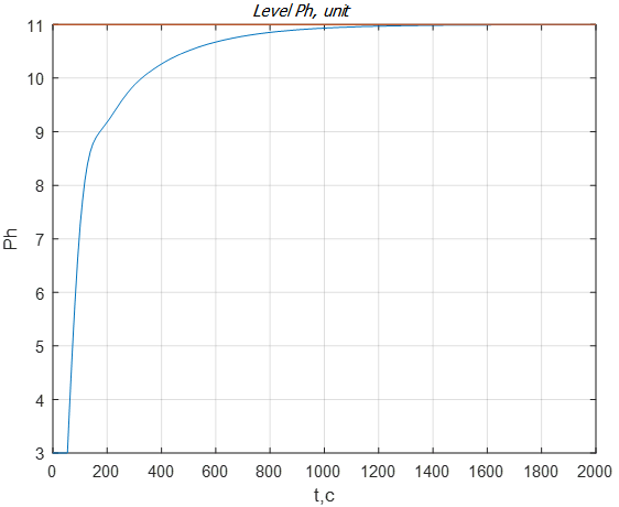
Figure 8 – Graph of the transient pH level
From the graph of Fig. 8. it is seen that the system meets the requirements of the quality of regulation: the regulation time is tp = 20 min, there is no overshoot, ? = 0%.
Let us analyze the reaction of ATS to a possible change in the consumption of reagent of milk of lime. Changes in reagent consumption are usually modeled as a step signal. In practice, in real conditions of ATS functioning, sharp loads are not permissible, however stepwise signals are useful from the point of view of testing synthesized controllers for working out possible disturbances. Suppose, at a time of 1200 s, the reagent consumption changed from 40 m3/s to 35 m3/s (Fig. 9). This suggests that the purified water will become more neutral, as evidenced by a pH level that decreases to 10 units. From the graph of Fig. 9 it is seen that the system fulfills the disturbance in the supply of the reagent in 20 minutes, which corresponds to the requirements for objects of this class.
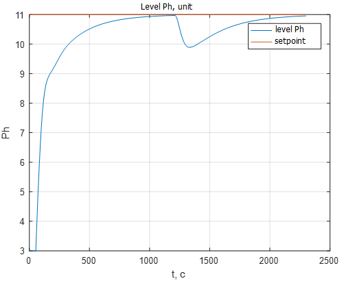
Figure 9 – The transition process of the pH level when changing the flow of milk of lime from 40 m3/s to 35 m3/s
Figure 10 shows the transient graphs of the flow rate of the source water, as well as the progress of the regulatory body.
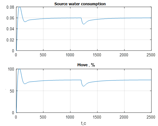
Figure 10 – Transients of the flow rate of the source water and the course of the RB
The graphs in Fig. 10 confirm the correct functioning of the ATS. With a decrease in reagent consumption, the flow rate of the source water also decreases in order to avoid obtaining an acidic environment. At the same time, the RO operates in the normal mode in the region of 70%, which makes it possible to work out disturbances both for opening and closing. With the perturbation under consideration, the RO closes slightly in order to reduce the flow rate of the regulated flow of the source water. [8]
The graphs in Fig. 11 show the outputs of the external circuit regulators – the pH level and the internal circuit – the flow rate of the source water.
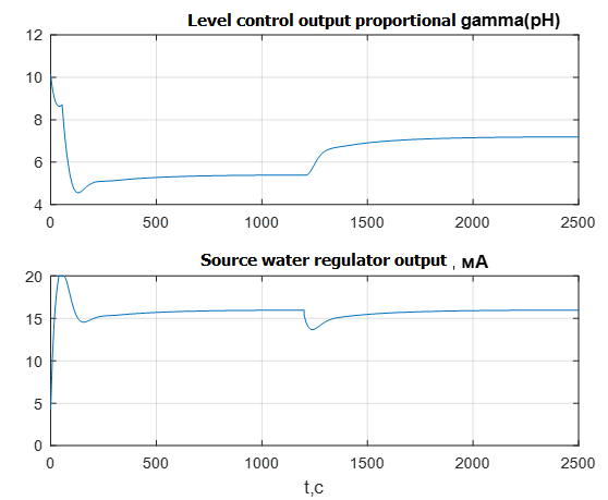
Figure 11 – Transients of the output signals of the regulators of the external and internal circuits
The output signal of the external pH regulator (Fig. 11) actually sets the ratio of the flows of the source water and milk of lime. From the upper graph it follows that the coefficient of the ratio of flows is about 5 units. With a decrease in reagent consumption, the pH regulator, seeking to restore a given pH level, fulfills increases the ratio with 5 units. up to 7 units When modeling, the output signal of the level controller is limited by the possible range of variation of the ratio.
The output signal of the source water flow regulator (Fig. 11) is also limited by the required range of 4..20mA and does not exceed the limits when processing disturbances, which makes it possible for the technical implementation of this control scheme.
Fig. 12 shows a graph of the transition process of the pH level, reflecting the change in the setpoint for pH. At time 2500 s. there is a step change in setting the pH level with 10 units. up to 8 units The change in the setpoint signal of the ATS fulfills in 15 minutes, which corresponds to the specified requirements.
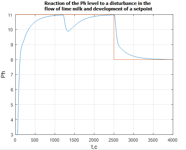
Figure 12 – pH transient when the setpoint signal changes
Conclusions
1. A mathematical model of the neutralization process is obtained, which is an inertial object with a transitional delay, as well as a mathematical model of the actuator, the regulatory body, taking into account the real technological restrictions on the input and output signals.
2. Compiled a comprehensive model of the ATS, which is a cascade bypass. A synthesis of ATS has been completed. The PID – law is chosen as the laws of regulation on the control channel, the pH level — the flow rate of the source water , and the PI – law is used on the regulator channel of the ratio of the flows of the source water and the milk of lime. [9–10] The parameters of the regulators were automatically optimized using the PID – control block.
3. The simulation results show the performance of the ATS and the possibility of using the developed systems, the main quality indicators of which are:
– lack of static error;
– regulation time – about 20 minutes;
– aperiodic nature of transients without overshoot
– a satisfactory time for processing the signals of the settings and disturbances;
– compensation of both controlled and uncontrolled disturbances due to the selected deviation control principle.
References
- Моисеев Б.В. Водоподготовка и водный режим котельных установок: Учебное пособие для студентов очной и заочной формы обучения, специальности 140104
Промышленная теплоэнергетика
к курсовой и дипломной работе поКотельным установкам и парогенераторам
. — Тюмень: ГОУ ВПО ТюмГАСУ, 2010. — 79 с. - Водоподготовка : Процессы и аппараты : Учеб. пособие для вузов / Под ред. О.И. Мартыновой. — М. : Атомиздат, 1977. — 352 с.
- Л.О. Штриплинг, Ф.П. Туренко Основы очистки сточных вод и переработки твердых отходов Учебное пособие — Омск: Изд–во ОмГТУ, 2005. — 192 с.
- Беспалов А.В., Харитонов Н.И. Системы управления химико–технологическими процессами: Учебное пособие для вузов. — М.: ИКЦ «Академика», 2005. — 690 с.
- Методы и сооружения для отчистки сточных промышленных вод.
- В.Д. Дмитриев Эксплуатация систем водоснабжения, канализации и газоснабжения. М.:
Книга по требованию
, 2005, с.379. - В. Денисенко ПИД регуляторы: вопросы реализации (часть вторая): Журнал
Современные технологии автоматизации
. - Глинков Г.М. и др. Контроль и автоматизация металлургических процессов: Учеб. для ВУЗов/ Глинков Г.М. Косырев А.А. Шевцов Е.К. ; Под науч. ред. Глинкова Г.М. — М. : Металлургия 1989. — 352с.
- Клюев, А.С., Товарнов А.Г. Наладка систем автоматического регулирования котлоагрегатов. М.,
Энергия
, 1970г. — 270 с. - Чистяков В.С. Краткий справочник по теплотехническим измерениям. — М: Энергоатомиздат, 1990 — 320с.