Abstract
An advanced aspheric and asymmetric large aperture dielectric lens antenna is proposed firstly here for high resolution at W- band frequency. Large aperture and aspheric lens provides minimum focusing error and high resolution in millimeter wave quasi-optics application. To the best of the authors’ knowledge we design first time 500 mm large aperture lens for W-band quasi optics application. Near field radiation pattern, beam size and focal length of the lens are obtained theoretically and experimentally as well. Dielectric rod waveguide antenna is also designed and employed as a source antenna for the lens. The measured and simulated results of the DRW antenna also show very good performance at W-band frequency, and it has 15.3 dB gain with ?22.5 dB sidelobe levels at 94 GHz.
1. Introduction
Recently, millimeter wave applications are rapidly increasing in modern wireless systems such as uncompressed HD-TV transmission, radio astronomy, collision avoidance devices and image sensing radiometer. At these frequencies lenses become adequate in size and weight for many applications. Lens antennas consist of two main parts: the feeding antenna that can be any type of antenna or antenna array and lens that collimate incident divergent energy to prevent it from spreading in undesired directions. This kind of arrangement at millimeter wave frequency is known as quasi-optics [1–3]. At millimeter wave, the beam radius is smaller in wavelengths, and therefore the beam diffracts strongly. The critical parameters of the quasi-optics include antenna gain, beam size, and beam quality over the range of scanned angles. Various types of feeding antennas of the lens, such as horns, dipoles, planar, dielectric rod antenna, have been studied widely and used for achieving a compact size and high radiation efficiency. So far, the most practical structure is a dielectric rod antenna due to its low cross polarization, relatively high gain and potential for a very dense packaging [4–6]. In the case of lens antenna design, primarily two different lenses are used for realizing different goals. Canonical (hyperbolical, bi-hyperbolical, elliptical, hemispherical . . . ) or shaped lens antennas are used for collimating the radiated energy, or, in the case of shaped designs, for shaping the beam to required radiation patterns, while cylindrical and spherical lenses are mostly used for beam scanning with single, or multiple feed possibility [7–9].
The main objective of this paper is to present very large aperture (500 mm) aspheric dielectric lens antenna to obtain high resolution beam which fulfills compact quasi-optics requirements for image sensing. It has aspheric bi-convex surfaces to keep the beam quality from the aberration. The proposed lens is a design using commercial software CODE-V provided by optical research associates [10]. Further, the prototype of the lens and DRW antenna is fabricated and measured. The near field pattern, focal length and beam size of the lens are obtained experimentally. High gain and very low side lobes dielectric rod waveguide (DRW) antenna is used as a feed of the lens. Measured and simulated radiation patterns and return loss of the DRW antenna are presented in the further sections.
2.ASPHERIC LENS ANTENNA DESIGN
Aspheric dielectric lens antenna geometry is shown in Fig. 1. To obtain low aberration loss of the lens, it is designed with biconvex aspheric surfaces using optics simulator, CODE V [8]. Eq. (1) shows the design formula for side-I and side-II aspheric surface of the proposed lens. This empirical equation is obtained by curve fitting of the lens surfaces.
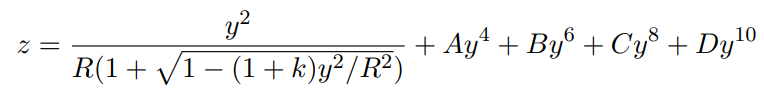
where, y and z are the design coordinates of the surfaces. A, B, C, D, R and k are the constants for both surfaces. The values of the constants for both surfaces are given in Table 1. The centre thickness of the lens is about 145 mm, and edge thickness of the lens is 20 mm as shown in Fig. 1. Fabricated lens antenna is shown in Fig. 2. Material of the lens is HDPE (high density polyethylene) which has dielectric constant
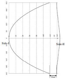
Fig. 1
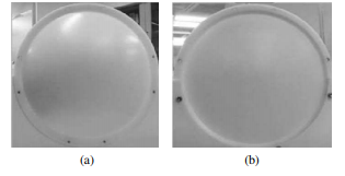
Fig. 2
Table 1
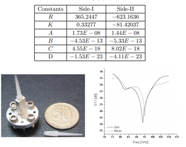
Fig. 3
DRW ANTENNA DESIGN AND MEASUREMENTS
A modified version of the tapered DRW antenna is shown in Fig. 3. The antenna is built of a 7? long (at Centre frequency 94 GHz) tapered dielectric rod and a conventional metallic waveguide (WR-10) with a junction or matching part between the rod and waveguide. Inner dimension of the junction part of the metallic waveguide is slightly wider (2.54 1.5 mm2) than the remaining waveguide (2.54 1.27 mm2) to improve the return loss. The dielectric rod is constructed by HDPE, same material characteristic as lens dielectric. The above mentioned antenna is also simulated using CST electromagnetic simulator. Details of the DRW antenna design have been described in [11]. Simulated and measured return loss of the above mentioned feed antenna is shown in Fig. 4 at W-band frequency. It shows ?15 dB return-loss over the W-band (75–110 GHz) and ?21 dB return
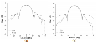
Fig. 3 – (a) E-plane, (b) H-plane. Radiation gain of DRW at 94 GHz.
loss at desired 90 to 100 GHz frequency band. It shows a well matching between the measured and simulated results except frequency shifted towards higher side of the measured return loss due to imprecise electrical parameter of the HDPE material at millimeter wave frequency. The E and H-field radiation patterns are depicted in Fig. 5(a) and Fig. 5(b) at 94 GHz frequency. Apart from the slightly higher side lobes in the measurement results, good agreement between measured and simulated results can be observed. It can be observed from the figures that the antenna has gain about 15.3 dB and 10 dB beam-width of 53.2? and 48.6? at each E and H-plane. The measured side lobe labels of the DRW antenna differ from the simulation results in Fig. 5 due to fabrication error of the dielectric rod. The molding of the dielectric rod highly influence the radiation pattern of the DRW antenna at W-band. The following section evaluates the quasi-optics performance of the above mentioned lens and DRW antenna.
CONCLUSION
Large aperture aspheric dielectric lens is proposed for quasi-optics design at millimeter wave W-band focal plane imaging system. Prototype of the lens and DRW antenna was fabricated and measured. DRW antenna has gain of 15.3 dB; 10 dB beam-width is 48.6? and SLL of 22.5 dB in H-plane at 94 GHz. Its beam pattern is nearly circular. The E- and H-field patterns are almost the same. Measured result of the quasi-optics shows that the dielectric lens antenna has focal length about 427 mm and H-plane 3 dB beam size about 3 mm.
REFERENCES
1. Goldsmith, P. F., et al., “Focal plane imaging systems for millimeter wavelengths,” IEEE Trans. Microwave Theory Tech., Vol. 41, 1664–1675, 1993.
2. Goldsmith, P. F., Quasioptical System — Gaussian Beam Quasioptical Propagation and Applications, IEEE Press, 1998.
3. Schwarz, S. E., “Efficiency of quasi-optical couplers,” Int. Journal of Infrared and Millimeter Wave, Vol. 5, 1517–1525, 1984.
4. Shiau, Y., “Dielectric rod antennas for millimeter-wave integrated circuits,” IEEE Trans. Microwave Theory Tech., Vol. 24, 869–872, 1976.
5. Lioubtchenko, D. V., S. N. Dudorov, J. A. Mallat, and A. V. Raisanen, “Dielectric rod waveguide antenna for W-band with good input match,” IEEE Microwave and Wireless Comp. Lett., Vol. 15, 4–6, 2005.
6. Patrovsky, A. and K. Wu, “94-GHz planar dielectric rod antenna with substrate integrated image guide (SIIG) feeding,” IEEE Antennas and Wireless Propag. Letters, Vol. 5, 435–437, 2006.
7. Tuovinen, J., T. M. Hirvonen, and A. V. Raisanen, “Near-field analysis of a thick lens and horn combination: Theory and measurements,” IEEE Trans. Antennas Propag., Vol. 40, 613–619, 1992.
8. Tajima, Y. and Y. Yamada, “Improvement of beam scanning characteristics of a dielectric lens antenna by array feeds,” IEICE Trans. Fundamentals, Vol. E91-A, 1616–1624, 2008.
9. Sun, Z. L. and W. B. Dou, “Far-field pattern of a focal-plan array-lens at millimeter wavelengths,” Int. Journal of Infrared and Millimeter Waves, Vol. 19, 673–685. 1998.
10. http://www.opticalres.com/.
11. Kim, W.-G., J. P. Thakur, and Y. H. Kim, “Efficient DRW antenna for quasi-optics feed in W-band imaging radiometer system,” Microwave and Optical Tech. Letters, Vol. 52, 1221–1223, 2010.