Abstract
Content
- Introduction
- 1. Relevance of the topic
- 2. The purpose and objectives of the study
- 3. Choosing a sensor for motion capture
- 3.1 Kinect
- 3.2 Asus Xtion Pro
- 4. The principle of operation of the main components of the sensor
- 4.1 Connection and preparation for work
- 4.2 How the depth camera works
- 4.3 Obtaining information about human joints and building a skeleton map
- 5. Transferring data from a program written in C# to Matlab
- 6. Voice control implementation
- 7. Creation of a user interface for selecting an operating mode.
- 8. Model creation in MSC Adams.
- Conclusions
- References
Introduction
Computer vision is one of the most promising areas in robotics. Thanks to its stereo vision capabilities, a robotic device can:
- Assess obstacles in your path.
- Find the required objects among many objects.
- Identify human joints.
- Get the coordinates of the desired object and much more.
Also, computer vision can be used as a trajectory planning algorithm for an electromechanical device.
1. Relevance of the topic
Certain mechanical systems require a trajectory planning link for their normal functioning, which allows adjusting the motion algorithm of the controlled object in accordance with the design features.
2. The purpose and objectives of the study
The purpose of the work is to create an algorithm for planning a trajectory for the musculoskeletal system of an anthropomorphic robot. The relative position of the joints of the right hand will be used as a reference device.
3. Choosing a sensor for motion capture
The modern market provides many products for the implementation of the task. The most basic and suitable sensors in terms of their functionality should be considered.
3.1 Kinect
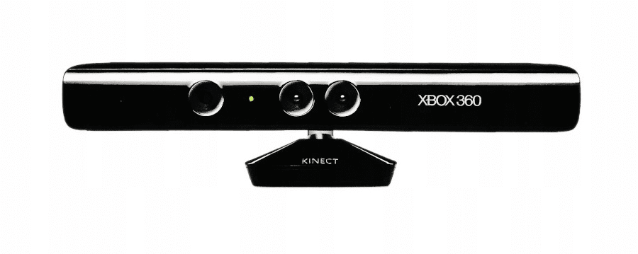
Initially, the developers set themselves the task of creating a contactless game controller that would be a good addition to the Xbox 360 game console [1]. Figure 3.1 shows the appearance of the device.

Figure 3.1 – Kinect for Xbox 360 appearance
However, now, the Kinect is more associated with a device that has little to do with the gaming industry.
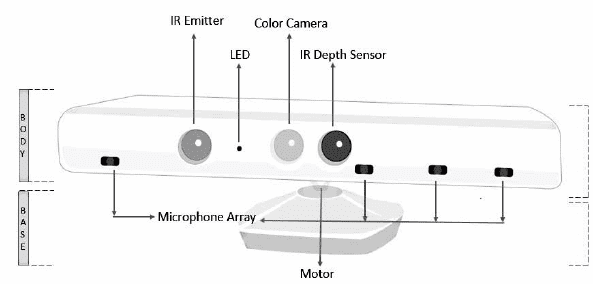
Figure 3.2 shows the local location of the sensor components.

Figure 3.2 – The location of the working bodies of the sensor
From Figure 3.2 we have the following components[2]:
- IR Emitter – infrared projector.
- LED – light-emitting diode. Needed to indicate the health of the sensor and software.
- Color Camera – RGB‑camera:
- 30 frames per second at 640x480;
- 12 frames per second at 1280х960.
- IR Depth Sensor – infrared camera.
- Microphone Array – microphone grill. Consists of 4 microphones.
- Motor.
The motor allows you to rotate the body relative to the base by ± 27 °
3.2 Asus Xtion Pro
Figure 3.3 shows the appearance of the sensor with the location of its main parts [3].

Figure 3.3 – The appearance of the Asus Xtion sensor
It should be noted that the technology of motion capture in this sensor is exactly the same as in the Kinect. Compared to the previous analogue, due to the minimization of the number of cameras, it has a small size. This makes it more common in applications where installing a large sensor is either impossible or impractical.
4. The principle of operation of the main components of the sensor
To write the appropriate program for the Kinect Xbox 360, you must first understand the principle of operation of the main elements.
4.1 Connection and preparation for work
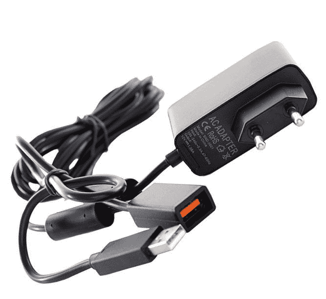
To connect this sensor, you need a special adapter (Figure 4.1).

Figure 4.1 – Required adapter for connection to PC
Due to the fact that the software on which the computer and the controller itself are running are products of the same company. Therefore, Microsoft has released full support for its Kinect for Windows SDK[4] product.
It is worth noting that there are also other libraries that allow you to program the sensor as needed (OpenNI, OpenKinect, KinectPy, Coding4Fun[5]).
4.2 How the depth camera works
Basically, a depth camera is used to isolate objects and obtain information about the distance to them. It should be noted that the most important of the main elements of the sensor is the depth camera (Figure 4.2).
Figure 4.2 – Obtaining the coordinates of an object
4.3 Obtaining information about human joints and building a skeleton map
When a user needs to get data about a skeleton, he will need to open a separate thread to process and obtain the necessary information[6]. When the device receives a request for information about the user's skeleton, it begins to request raw data from the depth camera.
As a result of the algorithm execution, the sensor receives data about the joints of the human body and allows you to work with them (Figure 4.3).
Figure 4.3 – Approximate map
of the tracked skeleton
As a result, the data obtained will be used to calculate the angle between the joints of the right hand.
5. Transferring data from a program written in C# to Matlab
The serial communication port will be used for data transmission. You will need to generate data (task angle for the robot) and send them to the STM32F407VE board. In order to form a data packet and send it over the serial port, the System.IO.Ports[7] namespace must be connected. This namespace allows you to initialize and work with the serial port.
6. Voice control implementation
In view of the need for direct control of the robot with the help of an operator, the task of realizing control of the behavior of the device and the program as a whole remotely appeared. The Kinect sensor has a microphone array for good voice recognition.
To implement voice control using Kinect, follow the steps:
- Make the sensor the default recording device.
- Connect the library in Visual Studio to recognize voice commands (in this case, the native Microsoft Speech Platform [8] library was used).
- Initialize a handler for voice commands.
7. Creation of a user interface for selecting an operating mode
To work with the device and form a task for the robot, it was necessary to create a user interface that would simplify the work with the sensor and make the control more interactive (Figure 7.1).
Figure 7.1 – Welcome window at application launch
8. Model creation in MSC Adams
At present, it is very important to be able to use various programs that allow simulating various mechanisms. Indeed, with the increase in the complexity of their design, the risk of errors in the calculations and construction of this model increases.
MSC.ADAMS [9] is based on a highly efficient preprocessor and a set of solvers. The preprocessor provides both the import of geometric primitives from many CAD systems, and the creation of solid models directly in the MSC.ADAMS environment.
Figure 8.1 shows an imported model in the Adams environment.
Figure 8.1 – Imported model appearance
Given the input data for each part, the Adams built-in solver will calculate the required moments of inertia and determine the center of mass. Next, you need to specify the connections between the parts. The environment has the following connection options. Figure 8.2 shows an example of adding a Revolute Joint link.
Figure 8.2 – Establishing connections between parts
When all connections are established, the law of motion for each joint of the robot should be indicated.

Figure 8.3 – Working out the squat task
(animation: 14 frames, 7 cycles of repetition, 368 kB)
Conclusions
As a result of the development of the trajectory planning algorithm, the tasks were set to implement the considered principle in practice, to write the appropriate software for combining the main nodes necessary for work. The principle of modeling in the MSC Adams environment is considered, as well as the addition of a connection with the Matlab package. This allowed us to combine the strengths of the two tools and get a high-quality simulation result.
References
- ќфициальна€ страница Kinect. [Ёлектронный ресурс]. – –ежим доступа: https://azure.microsoft.com/ru-ru/services/kinect-dk/
- “ехнические характеристики контроллера Kinect. [Ёлектронный ресурс]. – –ежим доступа: https://3dnews.ru/594561
- ќфициальный сайт Asus Xtion Pro. [Ёлектронный ресурс]. – –ежим доступа: https://www.asus.com/ru/3D-Sensor/Xtion_PRO_LIVE/
- Ѕиблиотека Kinect for Windows SDK [Ёлектронный ресурс]. – –ежим доступа: https://www.microsoft.com/en-ie/download/details.aspx?id=40278
- Ѕиблиотека Coding4Fun [Ёлектронный ресурс]. – –ежим доступа: https://archive.codeplex.com/?p=c4fkinect
- ќсновы отслеживани€ данных тела человека [Ёлектронный ресурс]. – –ежим доступа: https://habr.com/ru/post/151296/
- Ѕиблиотека дл€ работы с последовательным портом в C# [Ёлектронный ресурс]. – –ежим доступа: https://docs.microsoft.com/ru-ru/dotnet/api/system.io.ports.serialport?view=netframework-4.8
- Ѕиблиотека дл€ реализации голосового управлени€ [Ёлектронный ресурс]. – –ежим доступа: https://www.microsoft.com/en-us/download/details.aspx?id=27225
- ќфициальный сайт продукта MSC Adams [Ёлектронный ресурс]. – –ежим доступа: https://www.mscsoftware.com/product/adams


