
Abstract
Content
- Introduction
- 1. Relevance of the topic
- 2. Purpose and objectives of the study, planned results
- 3. Study overview
- 3.1 Construction and principle of operation of the hydraulic elevator
- 3.2 General provisions
- 3.3 Compressed flow simulation in a three–stage diffuser
- Conclusions
- List of sources
Introduction
Jet devices (pumps) are widely used in the design of hydraulic transport systems in construction, agriculture, power steam turbine plants, fire fighting equipment (as mixers), in the chemical industry and have acquired particular importance in the mining industry.[2]
This is due to the simplicity of design and high reliability, since there are no moving mechanical parts in the design of jet devices, this greatly simplifies the conditions of its operation and facilitates its repair and maintenance. The use of jet devices in many branches of technology makes it possible to obtain simpler, more efficient and reliable technical solutions in comparison with the use of mechanical blowers (compressors, pumps, gas blowers, fans, etc.).[3][4]
Hydrojet pumps are devices designed to implement the process of mutual movement of a jet of a working (active) liquid with a flow of a sucked (passive) medium and their subsequent joint transportation. The passive medium can be a liquid, a gas or a slurry containing, in addition to the liquid, solid or gaseous dispersed impurities. It follows from this that external energy is supplied to the hydraulic jet pumps by the working fluid.[5]
Hydro–jet devices got their wide distribution due to a number of advantages, namely:
- high self–priming ability;
- the ability to pump liquid, gases, gas-liquid mixtures, slurries containing solid impurities, aggressive media;
- no moving parts;
- simplicity of the device;
- small overall dimensions and weight;
- possibility of convenient placement in hard to reach places;
- ease of regulation of flow and pressure.
Unfortunately, water jet devices have significant disadvantages.:
- lack of autonomous drive;
- the need to use an external source of pressure fluid to drive;
- low installation efficiency, in the best designs no higher than 35 – 40 %
In the mining industry, it is impossible to do without drainage systems, which are designed to pump water out of mine workings, thus protecting the mine from flooding. One of the simplest, most effective and reliable methods is the use of hydroelevator drainage units.
Hydraulic elevators have become widespread and used in the cleaning methods of sump of the main and skip shafts of mines, because allows to provide a simpler and more reliable method, as well as significantly reduce the proportion of unskilled manual labor.[6]
1. Relevance of the topic
Liquid jet pumps are widely used in aircraft fuel supply systems, increasing the suction pressure of centrifugal pumps, hydraulic production and hydrotransport of solid and bulk materials, dewatering and drainage, technical water supply for turbines of hydroelectric power plants and many others. Moreover, in most hydraulic systems, ejectors operate for a long time under non – stationary conditions, for example, when the system is started or during its regulation.
In systems for drainage and emptying of tanks, the mode of operation of the ejector during the entire period of pumping is unsteady. Therefore, the effective use of an ejector requires a deep knowledge of the hydrodynamics of the working process, the static and dynamic characteristics of the apparatus. Research on the improvement of jet pumps for various purposes, carried out for a number of years at the Department of Power and Mechanical Systems
, indicate that jet pumps, having high reliability, in many cases consume excessively high volumes of working fluid and energy, and the ejection capabilities of non – stationary jets and devices based on them have not been sufficiently studied. The existing calculation methods are focused exclusively on the steady–state modes of operation of jet pumps with a continuous active jet, and transient modes typical for many hydraulic systems with jet pumps are practically not considered.[7]
2. Purpose and objectives of the study, planned results
The purpose of this work is to develop the parameters of a three – stage diffuser based on the task at hand, by simulating the flow path of the diffuser in an environment SolidWorks FlowSimulation
.
To achieve this goal, you must complete the tasks:
- Consider and analyze the physical processes taking place in a three – stage diffuser;
- Determine the features of the workflow and ways to improve work efficiency;
- Based on the results of the study, determine the parameters that increase the efficiency of the jet pump.
It is planned to develop a hydraulic elevator using this technology to clean the mine's skip shaft.
3. Study overview
3.1 Construction and principle of operation of the hydraulic elevator
Hydroelevator – This is a jet pump designed for lifting and transporting slurries and liquids through a pipeline. Picture 1 shows a diagram of the hydraulic elevator. The principle of operation of the hydraulic elevator is as follows: the energy of the flow of the working fluid is supplied through the pipeline by the working water 1, in the nozzle 3 of the hydraulic elevator is transformed into the kinetic energy of the jet. Part of the kinetic energy of the jet is used to move the flow of the transported liquid through the supply pipeline 8, to the receiving chamber 2 and the confuser 4 before the beginning of the mixing chamber 5.[1]
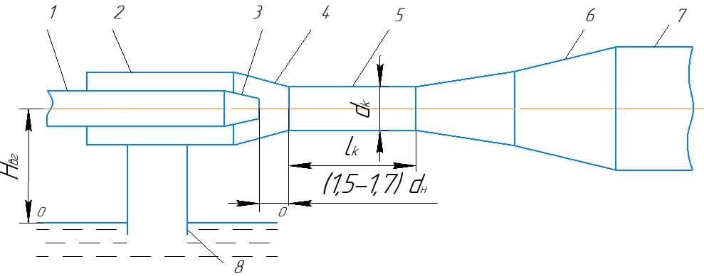
Picture 1 – Scheme of hydraulic elevator
Picture 2 – The principle of operation of the hydraulic elevator (animation: 31 frames, 10 repetitions, 144 kb)
In the process of mixing flows in the mixing chamber, the energy of the flow of the working fluid being transported is transferred. In this case, the speed of the working fluid decreases, and the transported one increases. The confuser serves to supply the transported liquid to the mixing chamber and increase its speed, which reduces energy losses during mixing of flows. In the diffuser 6 comes the transformation of the kinetic energy of the mixed flow into the potential energy 7 of the pressure required to move the flow through the pressure pipeline 7 of the hydraulic elevator.
Due to the simplicity of the design, the absence of rotating and rubbing surfaces, it ensures reliable and trouble–free operation on the slurry. A feature of using a hydraulic elevator is the use of unqualified maintenance and the constant presence of a person during work. In the event of air leaks, the hydraulic elevator continues to work without requiring shutdown and allows water to be pumped dry.
3.2 General provisions
For the transition from a smaller section of a pipe (channel) to a large one (converting the kinetic energy of the flow into potential or dynamic pressures into static ones) with a minimum loss of total pressure, a smoothly expanding section is installed – diffuser. Picture 3 shows the flow spectrum in diffusers with different expansion angles.
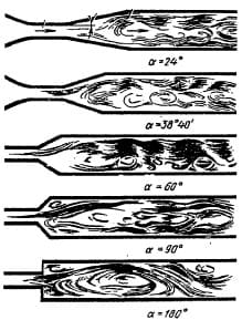
Picture 3 – Flow spectrum in diffusers with different expansion angles
Due to the fact that in a diffuser with an increase in the cross – sectional area, the average flow velocity decreases with an increase in the expansion angle, the total resistance coefficient of the diffuser, reduced to the velocity in a narrow (initial) section, becomes, up to certain limits, less than for the same length of a section of a pipe of constant cross–section with an area equal to the initial cross–sectional area of the diffuser.
Starting from a certain expansion angle of a diffuser of a given length, a further increase in this angle significantly increases the drag coefficient, so that it becomes many times greater than for a straight pipe of the same length.[8]
An increase in the drag coefficient of a diffuser of a given length with a further increase in the angle of expansion is caused by an increasing turbulent movement of the flow, separation of the boundary layer from the wall of the diffuser, and the associated strong vortex formation. The boundary layer is detached from the walls under the influence of a positive pressure gradient along the diffuser, which arises due to a decrease in velocity with an increase in the cross section (according to the Bernoulli equation).
With constant flow conditions at the inlet and α constant relative length or expansion ratio of the diffuser, an increase in the expansion angle, starting from α = 0 °, leads in succession to four main flow regimes:
- stable regime; continuous flow (
continuous
diffusers); - a regime with a large unsteady flow stall, when the size of the zone and the separation intensity change over time (a regime of strong pulsating flows, diffusers with local flow separation);
- fully developed flow separation mode, when the main part of the diffuser is occupied by a large zone of reverse circulation (diffusers with a significant flow separation);
- jet flow mode, in which the main flow is separated from the walls of the diffuser along the entire perimeter (diffusers with complete flow separation).
The onset of separation in the diffuser depends both on its geometric parameters and on the flow regime and the state of the flow at the inlet (thickness of displacement of the boundary layer or thickness loss of momentum
, degree of turbulence, etc.). Experiments show that in the presence of a diffuser with an angle of α = 4 °, placed both directly behind the smooth collector and far behind it, no separation of the flow is observed over the entire length of the diffuser, even over a length corresponding to the section with the area ratio.
As a increases α (up to 10 – 14 °), according to the same experiments, the value at which the core of constant velocities is still retained increases. At the same time, at the specified angles of expansion and certain lengths, flow separation appears even if the core remains constant.
The separation of the flow from the walls of diffusers with expansion angles of approximately α = 40 ° begins, as a rule, not along the entire perimeter of the section, but in the region where, for one reason or another (not the symmetry of the diffuser, the asymmetry of the velocity profile at the inlet and the flow velocity in As soon as separation occurs on one side of the diffuser, further increase in static pressure along the diffuser stops or weakens, and flow separation from the surface of the diffuser on the opposite side no longer occurs. This circumstance causes an asymmetric distribution of velocities over the cross sections diffusers.
In a symmetric diffuser with a symmetric inlet velocity profile, flow separation from the wall occurs alternately on one or the other side of the diffuser, which leads to significant fluctuations in the overall flow. At small angles of expansion (α <15 – 20 °), losses in curved diffusers become even greater than in rectilinear ones. Therefore, it is advisable to use curved diffusers only for large expansion angles.
3.3 Compressed flow simulation in a three – stage diffuser
Known diffuser containing conical and cylindrical pipes, stepwise connected to each other. However, this diffuser has a very high pressure loss. The closest in technical essence and the achieved effect to the proposed one is a diffuser containing at least three cylindrical pipes, stepwise connected to each other. However, the known diffuser has significant axial dimensions. The aim is to reduce the axial dimension of the diffuser.[10]
This object is achieved in that the outlet portion of each tube, except for the last downstream, located in the subsequent pipe to form an annular sinus. Picture 4 shows a schematic diagram of a diffuser.
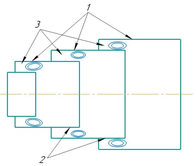
Picture 4 – Scheme of stepped diffuser
The diffuser contains three cylindrical nozzles 1, stepwise connected to each other. The outlet section 2 of each branch pipe, except for the last one in the direction of flow, is located in the subsequent branch pipe 1 with the formation of an annular cavity. The flow, passing from each previous section to the next, suddenly expands and breaks off, forming closed vortex cavities. The presence of sinuses 3 in the diffuser makes it possible to reduce its length, since a significant part of the separation region is located inside the sinus 3.
A diffuser containing at least three cylindrical nozzles connected in steps, characterized in that, in order to reduce the axial dimension, the outlet section of each nozzle, except for the last downstream, is located in the subsequent nozzle with the formation of an annular cavity.
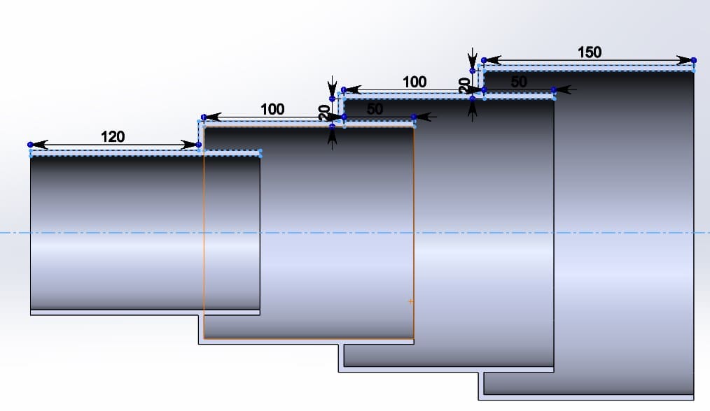
Picture 5 – Scheme of the constructed flow path of the diffuser
Using the internal function Flow Simulation, we start modeling the flow path of the diffuser based on Picture 5. To perform the simulation, it is necessary to create plugs at the inlet and outlet in order to create a closed volume of the model. We set the boundary conditions, in our case it is the volumetric flow rate of the hydraulic elevator and it is necessary to set the boundary pressure conditions.[9]
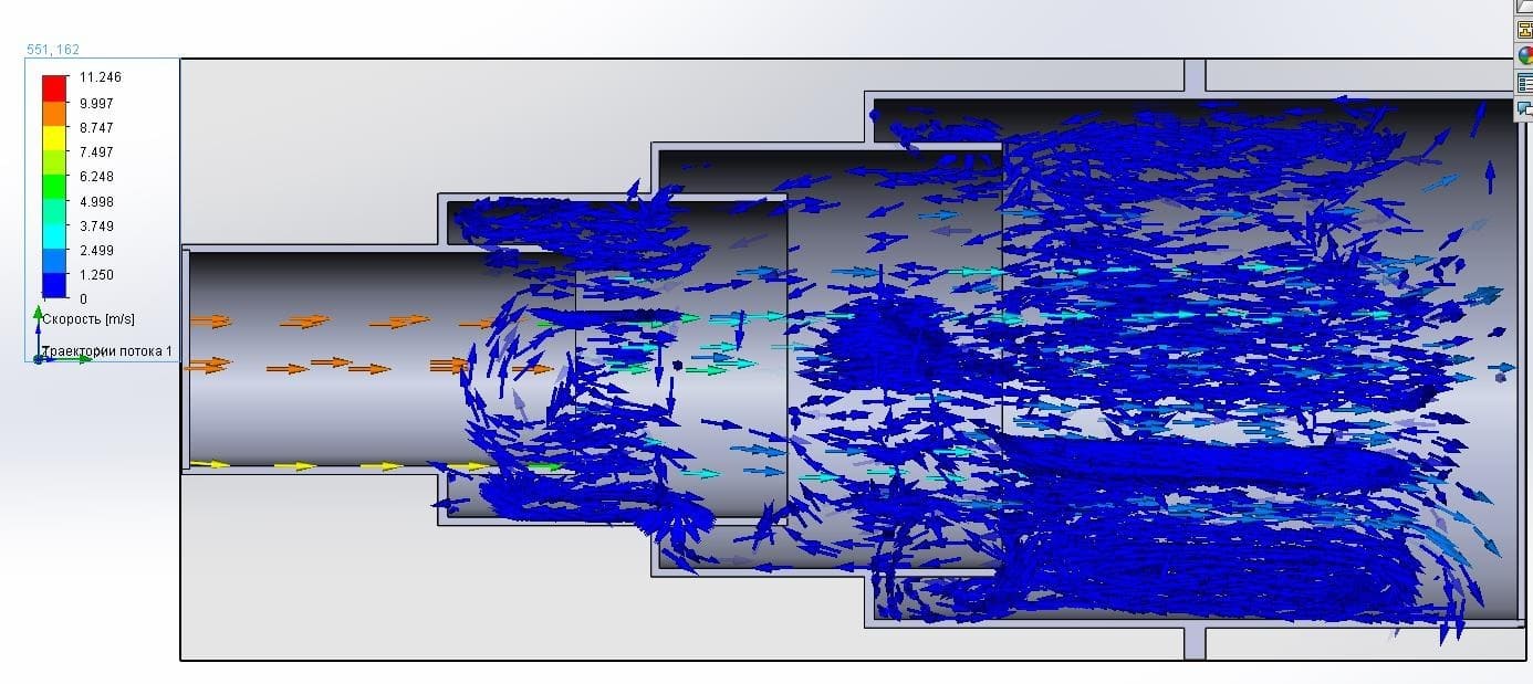
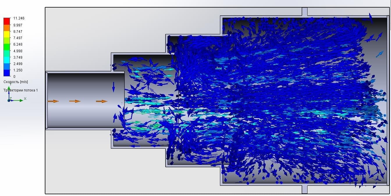
Note: Since the calculation is carried out in a closed space, an inaccuracy arises (the flow rests against the plug and creates a reverse flow), which prevents a full assessment of the simulation results. Therefore, we create a model of a diffuser with an outlet pipe section. Let's carry out a simulation with a change in the geometric parameters of the grooves (Lp – groove length; hp – groove height):
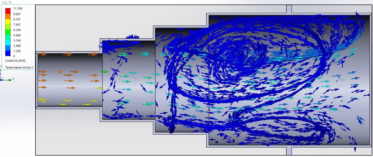
Picture 6 – Modeling with geometric parameters Lp = 0 mm; hp = 20mm.
Picture 7 – Modeling with geometric parameters Lp = 20 mm; hp = 20mm.
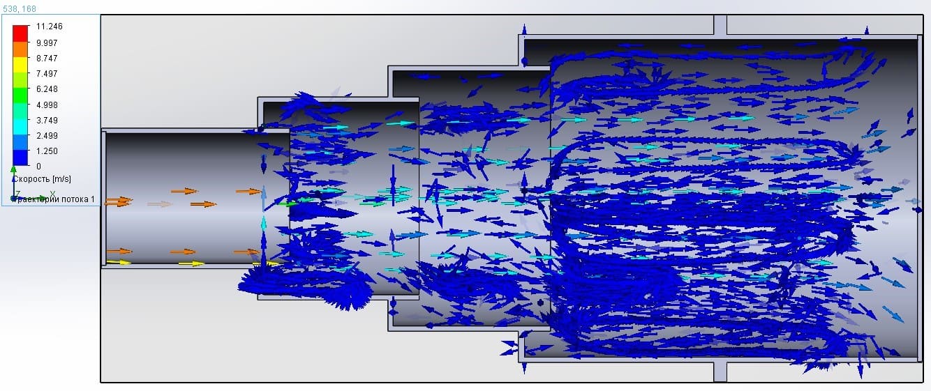
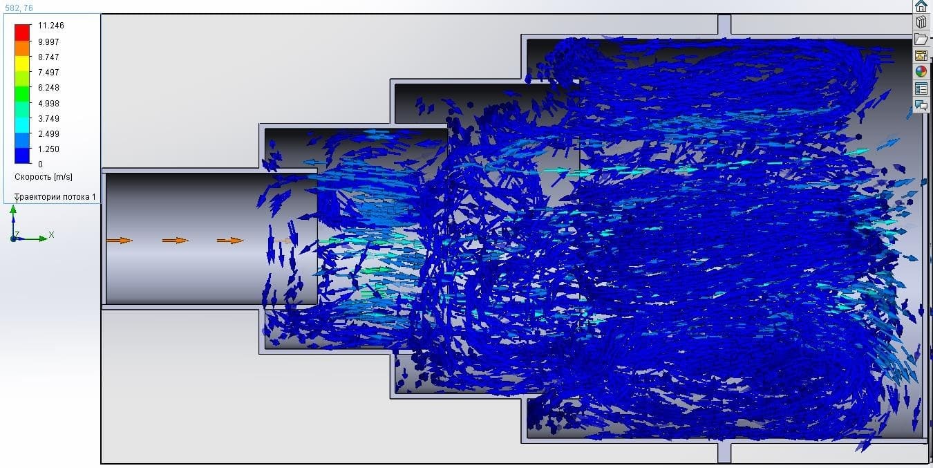
Picture 8 – Modeling with geometric parameters Lp = 40 mm; hp = 20mm.
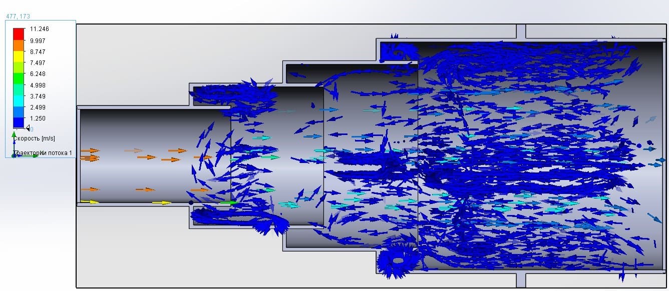
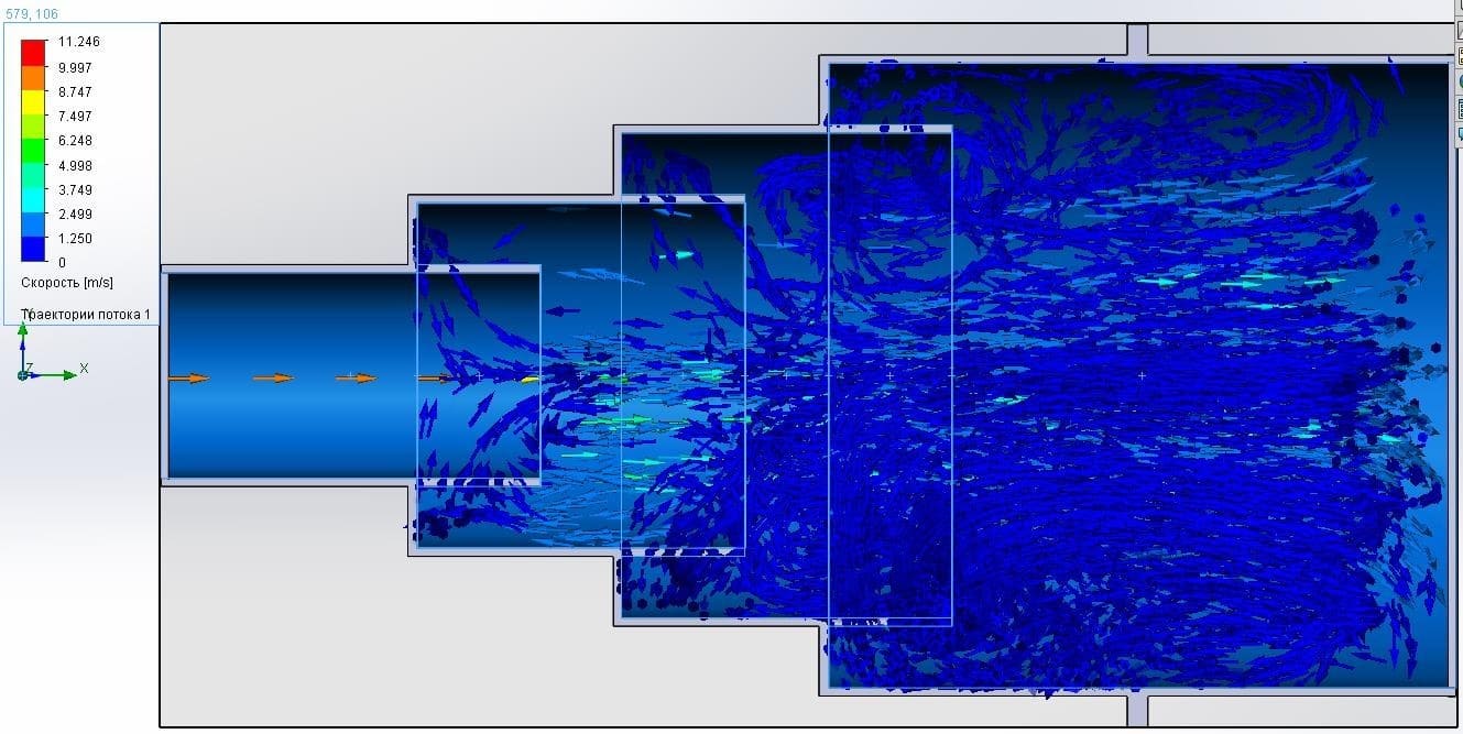
Picture 9 – Modeling with geometric parameters Lp = 60 mm; hp = 20mm.
Picture 10 – Modeling with geometric parameters Lp = 20 mm; hp = 30mm.
Picture 11 – Modeling with geometric parameters Lp = 40 mm; hp = 30mm.
Picture 12 – Modeling with geometric parameters Lp = 60 mm; hp = 30mm.
Conclusions
Based on the results obtained, it can be concluded that at Lp = 0 mm, a sharp expansion and separation of the flow occurs, which leads to high hydraulic losses and flow stall, picture 6, with an increase in Lp and hp, a sudden expansion and separation of the mixed flow occurs, forming closed vortex cavities in the grooves, which reduces the pressure loss in the diffuser. With insignificant values of Lp and hp relative to the geometric dimensions of the diffuser, only a small part of the flow forms closed vortex cavities, picture 6 and 10, when the optimal ratio of Lp and hp is reached, we observe a sudden expansion and separation of the mixed flow, forming closed vortex cavities in the grooves, and also that a part of the flow forming vortex cavities in the grooves contributes to the acceleration of the main flow, picture 8 and 12, with a further increase in Lp and hp, we observe only partial formation of vortex cavities, which leads to an increase in hydraulic resistance.
List of sources
- Козыряцкий Л. М., специальные средства и схемы гидроподъема, водоотлива и очистки шахтных водоотливных емкостей. // Учебное пособие / В. М. Моргунов, В. М. Яковлев, О. А. Геммерлшг – Донецк: ДонНТУ, 2012. – 133с
- Безуглов Н. Н. Гидроэлеваторы на угольных шахтах – М. – 1986.
- Гейер В. Г.,Тимошенко Г. М. Шахтные вентиляторные и водоотливные установки. М., Недра, 1987. – с. 270
- Кривцов А. Г., Шейнберг В. А. Анализ работы шахтных водосборников исследования трубистости их очистки / / проектирования и строитель-ства угольных предприятий. — 1975. – № 2 – с. 7–9.
- Куренков И. И. Расчет шахтных осветительных резервуаров и водосборников. – М.: Углетехиздат, 1951. – с. 39. Рабшович М. С. Подземные отстойники и механизация их очистки. – М.: ЦНТИ, 1955. –с. 32.
- Рабинович М. С. Подземные отстойники и механизация их очистки. – М.:ЦИТИ, 1955.-С. 32.
- Антонов Е. И., Жебеленко М. Г. Пак В. В. Совершенствование шахтных водосборников / Шахтное строительство. – 1986. – № 5 – с. 7–9.
- Сосновский П. Шахтные водоотстойники. – М.: Госпортехиздат, 1975. – с. 172.
- Попов В М. Водоотливные установки. Справочное пособие. М.: Над-ра. 1990. – с. 254.
- Научная электронная библиотека [Электронный ресурс]. – Режим доступа: https://www.elibrary.ru/item.asp?id=40098639.