Abstract. The article analyzes methods and means of measuring the flow of liquid media in pressure pipelines. After that, the conclusion is made which method is more promising for measuring flow in large-diameter pressure pipelines and its advantages are considered.
Keywords: Flow meter, converter, cross-section, flow rate, measurement, large diameter pipeline.
All flow measuring tools can be divided into two classes depending on the measurement method: direct flow measurement and indirect flow measurement.
Devices based on the first method measure directly the liquid flow in the pipeline [2]. Devices that implement the indirect method of flow measuring by the «speed-area» method determine the fluid flow rate in the pipe at one point of the cross-section of the pipeline and its area [1,2,4]. In the latter case, the flow measuring is based on the laws of turbulent fluid flow in the pipe, according to which the local flow velocity «V» at a point located at a distance [(0,242 ± 0,013) * R] from the inner surface of the pipe is equal to the average velocity of the fluid in this section – V = Vsr, and therefore is proportional to its flow rate.
Instruments that implement the direct flow measurement method.
Mechanical flow meters.
This group of devices includes all variable differential pressure sensors (standard orifices, nozzles, pipes and Venturi nozzles, etc.) [2].
A typical representative of variable differential pressure flow meters (Fig. 1), which is most widely used in the practice of flow measuring, is a Converter that uses a standard diaphragm as a narrowing device – a flat disk with a concentric hole in the center for the flow of the measured medium. On the inlet side of the flow, the aperture in the diaphragm is cylindrical, and on the outlet side it is conical.
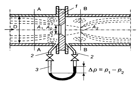
Figure 1 – Flow meter diagram of variable differential pressure
The diaphragm installed in the pipeline in the path of the fluid movement creates a pressure drop, by measuring which you can determine the volume flow [2].
These flow meters are widely used in industrial practice, due to the simplicity of their design. However, despite the wide variety of narrowing devices and specially designed designs, high accuracy of flow measurement with these measuring tools is not possible. The service life of most diaphragms does not exceed 3 years, since the input edge of the diaphragm is inevitably blunted during operation that reduces the output speed and the measured pressure drop. A negative flow measurement error is formed, which increases as much as the diaphragm is used [2].
In addition, the increased pressure drop that is created by the diaphragm to implement the measuring process leads to energy loss increasing for transporting the fluid through the pipeline. The use of flow meters with variable pressure drop is limited to areas where relatively low measurement accuracy is required. The maximum reduced error of these flow meters is rarely less than (1 ... 2) % [2].
In recent years, vortex flow meters are increasingly used for flow measuring (Fig. 2), based on the dependence of pressure pulsations frequency in the flow on the flow rate. The essence of the method is to create a stable vortex structure in the flow of a moving fluid, the excitation of which is achieved by twisting the flow or by flow around a stationary body of a special shape. There are several varieties of vortex flowmeters [2], but the final criterion of any design is the fluid pressure pulsations, which are characterized by the Reynolds number Re = VD/v, that is the ratio of inertia orces to the forces of viscous friction in the flow, and the Strouhal number Sh=f*d/V, which determines the periodic processes associated with the fluid moving.
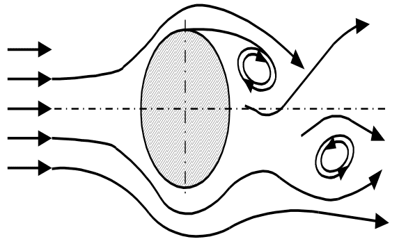
Figure 2 – Diagram of a vortex flow meter
Advantages of vortex flow meters are: linear conversion characteristics, high accuracy (error within * 0,5*1,5%), easy conversion, no moving parts, low inertia, frequency output signal. However, such flow meters with large pipeline diameters (over 250-300 mm) operate in the low-frequency region and do not provide stable vortex formation [2]. The disadvantages of vortex flow meters is the sensitivity to contamination of the measured medium.
Tools for measuring flow using the indirect method measurements
Of considerable interest for measuring the fluid flow in pressure pipelines of large diameter are devices whose operation is based on determination of volume fluid flow in the pipeline by the indirect method, i.e. the flow rate at one point of the pipeline cross section (the point of average velocity) and its area. As already noted, this measurement method is based on the laws of turbulent flow in pipes, according to which the local flow velocity V at a point located at a distance (0,242*0,013)*R from the inner surface of the pipeline is equal to the average axial velocity V = Vsr of the medium flow in this section, which means that it is proportional to the volume flow rate [1].
Flow meters with pressure devices
Flow meters with pressure devices are flow meters with a variable pressure drop. The essence of this method is to measure the dynamic and static pressure in the flow, the values of which determine the flow rate [4].
A classic example of a pressure device is the Pitot-Prandtl tube, which forms a pressure drop depending on the flow rate existing in the place where it is installed. Currently, Pitot-Prandtl tubes of various modifications are known, but their use for measuring local velocities in fluid flows is mainly limited to laboratory studies. This is primarily due to the requirement that the measured fluid is free of impurities and precipitation. Pitot-Prandtl tubes have a number of disadvantages, the main of which are a) high inertia; b) low sensitivity (about 15-20 cm/s); non-linearity of the calibration characteristic, especially affecting the measurement of low speeds – less than (3-5) m/s [3].
Flow meters with hydrometric turntables
Tachometric flow meters for large diameters pipelines (flow meters with hydrometric turntables) differ from conventional turbine flow meters in that their measuring device – turntables – is not affected by the entire flow, but only part of it. Practically flow meters with hydrometric turntables measure the flow at the cross - section point of the pipeline.
Flow meters with hydrometric turntables for pipelines of large diameters are characterized by insignificant head losses, which are caused by the placement of the primary speed measuring Converter (turntables) in the studied flow. This is their advantage.
The disadvantages of such devices include the presence of moving parts of the flow meter in the pipeline and, as a result, the need for a complex system of their lubrication. In comparison with pressure pipes, hydrometric turntables have large dimensions [2].
Flow meters with MHD converters
The need to measure the fluid flow in pipelines of large diameters is great and constantly increasing. Therefore, taking into account the advantages of electromagnetic flow meters when measuring the flow in large diameters pipelines, the interest in them is constantly increasing. However, the disadvantages of flow meters based on the direct measurement method, associated with large dimensions, the consumption of iron and copper, force us to abandon such measurement tools and pay attention to electromagnetic speed converters (MHD – converters) with a magnetic field localized in the zone of installation of sensitive electrodes. Such electromagnetic flow meters with a local magnetic field introduced into the flow are simpler and cheaper, and their advantage increases with the enlargement of the pipeline diameter. The magnetic field in the area of the sensitive electrodes of the Converter is created by a miniature coil fed by alternating current [3, 4]. Besides, to increase the sensitivity of the flow meter, various types of magnetic field concentrators located directly in the electrodes vicinity can be used [1].
The promise of electromagnetic flow meters with a local magnetic field is due to the fact that they have small dimensions, disrupt the flow minimally, are technological, durable, have a low metal content and low power consumption, are easily installed through standard entrances to continuous pipelines, etc. [2, 4]. High performance indicators of such flow meters rightfully place them among the most promising devices for measuring water flow in large diameters pipelines.
Conclusions
1. Currently, there are no reliable flow meters that provide reliable information about the fluid flow media in large pipelines and meet all the requirements for modern flow measurement tools.
2. Flow measurement tools can be divided into two classes: direct flow measurement and indirect flow measurement. Devices that implement the direct measuring method directly measure the flow of fluid in the pipeline; devices that implement the indirect measuring method determine the flow rate of fluid in the pipeline at one point of pipeline cross section (the point of average speed) and its area.
3. Measurement of fluid flow in filled pipes of large-diameter flow meters is based on the method of measuring the flow at one point of the pipeline cross-section and its area.
References
1. ГОСТ 8.439 – 81 Методика выполнения измерений методом площадь -
скорость. Введ. 23.09.81. – Изд-во стандартов, 1982. – 51 с.
2. Корсунский Л.М. Электромагнитные гидрометрические приборы. – М.:
Стандартгиз, 1964. – 180 с..
3. Кремлевский П.П. Расходомеры и счетчики количества вещества:
Справочник. - Кн. 2 –СПб.: Политехника, 2004. – 412 с.
4. Шерклиф Дж. Теория электромагнитного измерения расхода: Пер. с.
англ.– М.: Мир, 1965. – 268 с.
Аннотация. В статье проведен анализ методов и средств измерения расхода жидких сред в напорных трубопроводах. После чего сделан вывод какой метод более перспективен для измерения расхода в напорных трубопроводах большого диаметра, рассмотрены его достоинства.
Ключевые слова: расходомер, преобразователь, поперечное сечение, скорость потока, измерение, трубопровод большого диаметра.
Сведения об авторах:
Смешная Алина Вячеславовна – студент группы ПСм – 19, ДонНТУ
Кушниренко Елена Николаевна – ст.преподаватель кафедры английского языка, ДонНТУ