
Abstract
Content
Introduction
Computer technologies have long been included in our daily life. With their help, many processes are simplified, which used to take much of the time. For example, the exchange of information between people, receiving current news in all areas of life, complex mathematical calculations and much more.
In the modern world, computer technologies have long and confidently taken root in everyday life. They are designed to help a person cope with everyday tasks around the house, to perform the same type of work or tasks that require constant monitoring. Examples of such technologies can be “smart home” systems, as well as a huge variety of different devices that somehow make life easier for a person [1].
In the life of every person, a situation often happens when a stranger or a person familiar to him can come to his home at a time when he is not at home. Knowing about such events can often be helpful, be it a relative, friend, or just a stranger.
In this work, as a solution to such situations, a device for alerting the owner of an apartment about a visitor in real time is proposed. The device will also send an image of the person who came during the absence of the landlord.
1. Relevance of the topic
Our society has long been organized in pursuit of information. A modern person needs to know everything. From the weather forecast for the next week to the exchange rate on the stock exchange, from a new song by a popular artist to scientific discoveries. Every year, new ways of obtaining information are being developed, and the list of this very information that a person absorbs every day is expanding. Information that a few decades ago a person would have considered not necessary for study is now necessary for life in society.
In everyday life, one of the types of such information is information about people who come to our home. Any front door to an apartment has a pupil through which you can see who is behind the door. Modern technologies allow you to install video surveillance systems, intercoms and other devices to monitor and receive information about what is happening at your front door.
But it often happens that someone can come to our house during our absence, and we will not be able to find out about it. In everyday life, it can be helpful to always know that someone rang the doorbell right now, and also to see who did it.
2. Purpose and objectives of the study, planned results
Taking into account all of the above, the goal of this work is being formed - to create a device that, upon pressing the doorbell, will inform the owner of the apartment that someone rang the doorbell during his absence from home, and also send him a photo with a participant in this event.
The second goal is to study the developed device. Study of the image quality, possible sizes and formats of the image, as well as the speed of image acquisition, depending on many factors.
3. Device development
3.1 Block diagram of the notification device
The structural diagram of the host's visitor notification device is shown in picture 3.1.
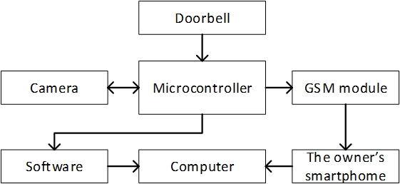
The block diagram of the device consists of the following elements:
- microcontroller;
- doorbell;
- camera;
- GSM module;
- software;
- computer;
- the owner's smartphone.
The device is controlled by a microcontroller (MC). A doorbell, a GSM module and a camera located at the front door are connected to the MC. The MC must be connected to the computer at all times, since it needs to transfer the image data received from the camera. The software processes the data from the camera and saves it to the computer as an image. The owner's smartphone is connected to the cloud service, which in turn is synchronized with the folder on the computer, which stores the received images.
The principle of operation of the device is as follows: a visitor comes and presses the doorbell. The MC receives the signal of pressing the doorbell and sends signals to the camera and the GSM module. The GSM module sends an SMS notification to the owner's smartphone that someone has called the doorbell. The camera generates a data stream and sends it to a computer through the MC, where the received data stream is processed in the program and an image in png format is formed from it, which is saved to a folder on the computer. The user can use his own smartphone and the Internet (mobile or Wi-Fi), and using the cloud service synchronized with the folder in which the images are stored, view the resulting image.

3.2 Selection and characterization of hardware
For optimal system performance and correct functionality, it is necessary to select hardware that will suit the task at hand. The following hardware was chosen for the visitor notification device:
- Arduino Nano board based on ATmega328P;
- camera module OV7670;
- GSM-module SIM800L;
- tact button as a doorbell.
These elements were chosen for several reasons: low cost, availability, ease of use. Here is a brief description of each element of the device.
3.2.1 Arduino Nano board
The Arduino Nano board is one of the smallest Arduino boards. It is a complete analogue of the Arduino Uno - it also works on the ATmega328P chip, but with a smaller form factor. Due to its overall dimensions, the board is often used in projects where compactness is important. There is no external power socket on the board, the Arduino Nano works via USB (miniUSB or microUSB). The rest of the parameters are the same as the Arduino Uno model [4]. A description of the main elements of the Arduino Nano board is shown in picture 3.2.

The Arduino Nano board has 14 digital pins, which are labeled with the letter D (digital). The pins are used as inputs and outputs, each with a pull-up resistor.
Analog contacts are designated with the letter A and are used as inputs. They have no pull-up resistors, they measure the voltage applied to them and return the value using analogRead().
3.2.2 OV7670 camera module
The OV7670 camera module, shown in picture 3.3, allows you to take VGA images with a maximum resolution of 640x480 pixels, perform their primary processing and transfer them to a control device, for example, an Arduino module, via the SCCB interface.

There are many settings for the OV7670. Image quality, data format and transmission mode are programmable. Image processing is configured by writing data to special registers of the OV7670 microcircuit using the SCCB interface - an analogue of the I2C bus. The sampling rate of 30 frames per second complies with the VGA standard. The frame rate is set by software. Also available formats: QVGA 320x240, CIF 352x240, QCIF 176x144.
It should be noted that the camera's capabilities are severely limited by the speed of the Arduino Nano board, in particular the ATmega328p microcontroller. Using this MC with this module, it is impossible to get a smooth image with a frequency of 30 frames per second and a resolution of 640x480px, due to the low frequency of the MC and a small amount of RAM. Nevertheless, this is enough to get one-time images in various formats and acceptable quality.
3.2.3 GSM module SIM800L
The SIM-800L module shown in picture 3.4 is a 4-band GSM / GPRS module, which is quite common and affordable for many radio amateurs.

The SIM800L module is based on the Mediatek ARM MT6261 chip. The 4-band RF7198 transceiver is responsible for GSM / GPRS communication [6].
Interaction with the module is carried out via the UART interface using special AT commands.
3.2.4 Other system elements
In addition to the above devices, this system will also need a solderless breadboard for debugging the entire system, resistors for correct connection and correct operation of some elements, a set of mom-dad and mom-mom jumpers for connecting system elements, as well as a clock button, when pressed, which will occur notification.
In this work, you will need 7 resistors: five - 10kOhm, one - 1kOhm, one - 680Ohm.
3.3 Software development
In this project, the software consists of 3 components:
- Arduino program (sketch);
- program for processing data from the camera and converting them into a finished image;
- cloud service.
Let's take a closer look at each software component.
3.3.1 Arduino program
A program written for the Arduino platform is called a sketch. To write the sketch, the official Arduino IDE was used. In this device, two modules and a button are connected to the Arduino board. Therefore, in the sketch it is necessary to organize the work of each module and the interaction between them. When someone presses the doorbell, the microcontroller reacts to this signal and accesses the camera module. A pixel-by-pixel transfer of one frame from the camera to the computer is performed via a USB cable via the UART interface. Color is RGB565 and grayscale is YUV422. In both cases, two bytes are required to transfer one pixel.
It is important to note that the process of reading pixels from the camera is extremely time-consuming, and any interruption that is triggered during this time will damage the image. Therefore, before transferring the frame, you must call a function that disables all interrupts.
3.3.2 Program for processing data from the camera
The data that the Arduino receives from the camera and sends through the USB cable to the computer needs to be received, processed, and formed into a finished image. All this should happen on the computer to which the Arduino itself is connected. For this, a special program was written in the Java programming language in the IntelliJ IDEA development environment.
This program consists of several files, they are also classes. Each class has its own functionality and purpose. The program implemented the receipt and processing of data from the camera with its subsequent transformation into an image, as well as saving the image to a computer in .png format.
3.3.3 Cloud service
In order for the user to be able to view the image taken by the camera at any time, a cloud service is required, or such services are also called cloud storage. This project uses the Yandex.Disk cloud service.
On the user's computer, Yandex.Disk appears as a regular folder. Everything in this folder is automatically synchronized with the cloud and other user's devices (phone, tablet, other PCs). Thus, when images received from the camera are saved to this folder, they can be viewed on another user's device, for example, a smartphone.
4. Device investigation
Using a solderless breadboard and jumpers to test and research the device, the necessary modules were connected to the Arduino Nano board (pic. 4.1).

So, let's test two image formats: RGB and grayscale. Both formats have a resolution of 320x240 pixels. After pressing the button, data is sent from the camera to the computer and the data is processed in a Java program. An RGB image was captured in 2.600 seconds (pic. 4.2), and a grayscale image was captured in 1.900 seconds (pic. 4.3). Also, both images were saved in the Image folder (pic. 4.4) and became available in the Yandex.Disk application on a smartphone (pic. 4.5).


Conclusions
At this stage of the master's work, a device for transmitting graphic information was developed, which makes it possible to notify the owner of the apartment about the visitor and send a photo of the visitor to the computer. Thanks to the use of the cloud service, the landlord can view the resulting image at any time using his own smartphone and the Internet. This device has been assembled and tested in real life and is fully functional. Also, initial research was carried out on the capabilities of this device, picture quality and data transfer rate. If necessary, this device can be adapted to the needs of a company or implemented as part of a security system.
References
- Информационные технологии в нашей жизни [Электронный ресурс]. – Режим доступа: [Ссылка]
- Обзорная статья по типам, видам и устройству домофонов [Электронный ресурс]. – Режим доступа: [Ссылка]
- Парфёнов Д.А. разработка системы приёма посетителей предприятия [Электронный ресурс]. – Режим доступа: [Ссылка]
- Плата Arduino Nano v 3.0 : распиновка, схемы, драйвера [Электронный ресурс]. – Режим доступа: [Ссылка]
- OV7670 модуль VGA камеры [Электронный ресурс]. – Режим доступа: [Ссылка]
- GSM-модуль SIM800L: самый полный мануал (на примерах с Arduino Uno) [Электронный ресурс]. – Режим доступа: [Ссылка]
- Уроки Fritzing [Электронный ресурс]. – Режим доступа: [Ссылка]
- SIM800L_Hardware_Design_V1.00 [Электронный ресурс]. – Режим доступа: [Ссылка]
- Пример работы с камерой OV7670 от пользователя Indrek [Электронный ресурс]. – Режим доступа: [Ссылка]
- Arduino OV7670 live image over USB to PC [Электронный ресурс]. – Режим доступа: [Ссылка]
- Уроки Arduino. Как написать скетч? [Электронный ресурс]. – Режим доступа: [Ссылка]
- Статья из Википедии о Java [Электронный ресурс]. – Режим доступа: [Ссылка]
- Статья из Википедии о IntelliJ IDEA [Электронный ресурс]. – Режим доступа: [Ссылка]