
Abstract
List of contents
- Introduction
- 1. Description of educational CAD (CAD_Electric_Education)
- 2. Modeling of the calculation scheme and its applications
- 3. Calculation of short circuit currents
- 4. Modeling of start-up and self-start modes of electric motors of the auxiliary system of a 300 MW unit
- Conclusion
- References
INTRODUCTION
The stable and economical operation of the power units of modern thermal power plants (TPPs) to a large extent directly depends on the reliability of the mechanisms of the auxiliary system. Auxiliary system of thermal power plants is a complex multi-machine system with a large number of step-down power transformers and cable-synchronous and asynchronous motor connections. The main type of drive for the most critical mechanisms at power plants are asynchronous motors with a stator voltage of 6 kV. A continuous increase in the unit power of the units leads to an increase in the installed power of the motor load, unit power and inrush currents of motors, which makes it difficult to ensure successful self-starting and dynamic stability of the motor load during short-circuit and short-term voltage drops. This can lead to an emergency shutdown of power plant units and a decrease in the reliability of the operation of the entire power system as a whole. In some transient modes (switching power to another source, short circuit disconnection), motors may experience stator current and electromagnetic torque surges that exceed the allowable and significantly reduce their service life, and, consequently, the cost of their maintenance.
1 DESCRIPTION OF EDUCATIONAL CAD (CAD_ELECTRIC_EDUCATION)
The most popular graphic editor AutoDeAutoCAD was used as a platform for creating CAD, in the environment of which a graphical database of images of the main elements of electrical circuits with a voltage above 1 kV was created. CAD software is built on the AutoCAD object model and uses the internal algorithmic programming languages AutoLisp, VisualLisp, as well as the DСL dialog box creation language.
The sources of the information taken are the latest developments in educational literature, as well as data from the official websites of leading equipment manufacturers (ABB, Simens, Shneider Electric, General Electric, Alstom Grid and others).
CAD software includes methods for solving systems of linear as well as non-linear algebraic equations by the square root method, which uses the symmetry property of coefficient matrices. A variant of the method for working with sparse matrices is applied, which leads to high speed of calculation functions.
2 MODELING OF THE CALCULATION SCHEME AND ITS APPLICATIONS
In this paper, as an example, the electrical part of ZuTES was modeled. The computer model of the TPP was created in the CAD_Electric_Education program. It consists of a graphic image of the electrical circuit, formed in the AutoCAD graphics editor, and the information support accompanying it. Figure 1 shows the graphic component of the computer model of the electrical part of the power plant. On it, for ease of finding electrical components, graphic blocks are used in the form of a dot with a number.
During the operation of the power plant, a different number of power units can be in operation. Especially often the circuit of the 6 kV auxiliary system is configured in connection with the possibility of supplying its sections with. n. power units from working or backup auxiliary transformers. To form variants of circuits with different composition of equipment in the design scheme, graphic blocks of switches are used. Imitation of their switching on the design scheme is carried out by replacing the graphic blocks of the switched on and off switches. When calculating transient electromechanical processes in the system of auxiliary needs (starts and self-starts of IM), to increase the speed of calculations, the equivalent of the entire power output circuit was applied in relation to one of the working or backup TSN. To determine this TSN, the circuit is analyzed programmatically, starting from the user-selected sections c. n., included their inputs and further according to the scheme to TSN. In addition, from the design scheme of the s.s. Elements not involved in the calculations are excluded. For this, an auxiliary test power supply mode for the load of sections c is simulated. n. from the selected TSN and then from the circuit, elements whose currents have zero values are excluded. The determination of voltages at the nodes of the circuit (see Fig. 1) in the calculation of transient processes is performed by the method of nodal potentials in a vector-matrix notation. Calculation of rotational speeds of aggregates p. n. in the start-up and self-start modes, it is carried out by solving the basic equation of motion of their rotors.
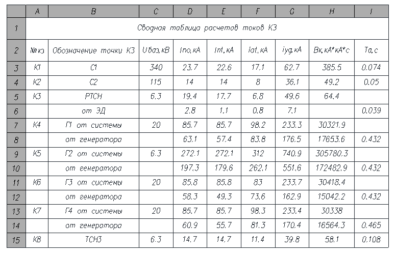
3 CALCULATION OF SHORT CIRCUIT CURRENTS
According to the computer model of ZuTES, short-circuit currents were calculated. In CAD, we document the data of the electrical elements of the circuit and calculate the short-circuit currents in pre-specified nodes of the circuit (Fig. 2).
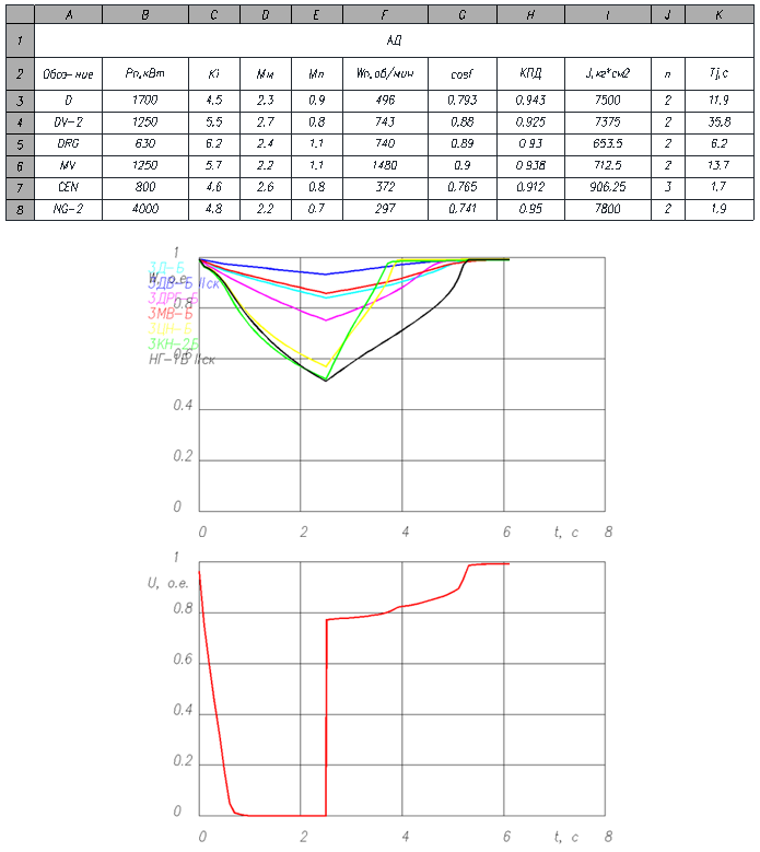
4 MODELING OF START-UP AND SELF-START MODES OF ELECTRIC MOTORS OF THE AUXILIARY SYSTEM OF A 300 MW UNIT
In the work, multi-variant calculations of the modes of starts and self-starts of the electric motor were performed. As an example, Figure 3 below shows the results of calculating the self-starting mode of the IM of section 3A of block No. 3 after a break in their power supply, which shows the curves for changing the rotational speeds and changing the voltage during the self-starting of the IM.
CONCLUSION
The master's thesis is devoted to the actual problem of researching the modes of starts and self-starts of electric motors in the auxiliary system with a voltage of 6 kV at TPPs with 300 MW units. The educational CAD system "CAD_Electric_Education", developed at the Department of Power Plants of the State Educational Educational Institution "DONNTU", which is an add-on for the AutoDesk® AutoCad graphic system, was chosen as the calculation system. With its help, calculations of short-circuit currents and verification of the main electrical equipment and current ducts were performed, both in the power distribution circuit and in the auxiliary system with a voltage of 6 kV. Also, mathematical modeling was performed on a PC using the CAD_Electric_Education software for starting and self-starting modes of the electric motors of the auxillary system of power unit No. 3 with a nominal capacity of 300 MW at Zuevskaya TPP.
REFERENCES
- Крючков, И. П. Расчет коротких замыканий и выбор электрооборудования: учеб. пособие для студ. учеб. заведений / И. П. Крючков, Б. Н. Неклепаев, В. А. Старшинов и др.; под ред. И. П. Крючкова и В. А. Старшинова. – 2-е изд., стер. – М.: Издательский центр Академия, 2006 – 416 с.
- Справочник по электроснабжению и электрооборудованию: в 2 т. Под общ. ред. А. А. Федорова. Т 2 Электрооборудование. - М.: Энергоатомиздат, 1987. – 592 с.
- Учебная САПР схем первичных электрических соединений станций и подстанций: учеб. пособие / В. А. Павлюков, С. Н. Ткаченко. – Донецк: Издательство ООО «НПП «Фолиант», 2021. – 264 с.
- Павлюков, В. А. Совершенствование методов идентификации параметров эквивалентных схем замещения глубокопазных асинхронных двигателей / В. А. Павлюков, С. Н. Ткаченко. – Электричество, 2018. – №10. – С.54-60.