
Abstract
Content
- Relevance of the topic
- Introduction
- 1. Causes and nature of damage to the main elements of power supply systems.
- 1.1 Overhead power lines
- 1.2 Cable power lines/a>
- 1.3 Power transformers
- 1.4 Relay protection and automation
- 2. Methods for calculating reliability indicators
- 2.1 Average item state probabilities
- 2.2 Probabilities of failure and non-failure state of circuits with serial connection of elements
- 2.3 Probabilities of failure and non-failure state of circuits with parallel connection of elements
- Bibliography
Relevance of the topic.
The relevance of this study is due to the high degree of depreciation (up to 80%) of the funds of the electric power industry (networks, distribution and control equipment), which, in turn, leads to a decrease in their reliability. The study of the reliability of electrical equipment of electrical networks allows solving one of the main tasks - supplying consumers with electrical energy in the required volume and standard quality. [1]Introduction.
Reliability is one of the main key performance indicators of any electric grid company. Approaches used to improve the reliability of electrical distribution networks are often empirical in nature, and as a result, do not bring the desired effect, taking into account the costs incurred. The study discusses the methodology for the formation of measures to improve the reliability of electrical networks. The proposed calculations make it possible to form various approaches to the implementation of tasks to improve reliability, ranging from the implementation of measures to improve elemental reliability and ending with the consideration of options for improving network reliability, at various levels of automation, taking into account their cost part and the level of achievable effect to reduce the failure rate parameter and the duration of outages [2].
Modern engineering methods for creating electrical networks and organizing their operation involve the use of quantitative estimates of reliability in order to rationally design electrical networks and create a highly efficient and economical system of operation.
The mathematical methods that have developed in the theory of reliability of electrical systems are mainly designed to solve reliability problems that arise at the level of individual devices and systems of a local nature, while not taking into account the possibilities and nature of operation. In fact, in power supply systems, one has to deal with large geographically distributed systems, the creation of an operation system for which must also take into account the availability and condition of roads, the provision of communications and telemechanics, the geographical location of repair and maintenance bases and the appointment of repair teams.[3].
The means of ensuring reliable power supply can be conditionally divided into technical and organizational and technical. Picture 1.
Figure 1. - Means of ensuring the reliability of power supply.
1. Causes and nature of damage to the main elements of power supply systems.
The operation of the power supply system can be represented as a continuous exchange of energy between the system and consumers when it is impossible to store it and unintentional interference with the system, leading to the failure of the elements, and in some cases the system as a whole.
The interactions between the power supply system and the external environment are stochastic in nature, and it is possible to speak of an uninterrupted supply of electricity only with a certain probability of achieving the goal. [4]
The most unreliable element of SES are power lines (TL) because of their great length and the influence of a large number of various external influences on them. In urban networks, about 85% of outages fall on power lines, and in rural networks - 90 ... 95%. A power line failure is any forced shutdown when it is damaged. [5].
1.1 Overhead power lines
Distinguish between stable damage to overhead lines (supports, wires, insulators) and unstable (self-healing). The latter are eliminated by the successful operation of automatic reclosing devices (AR) or manual closing [9].
The main causes of damage to overhead lines (VL) are: lightning flashing of insulation; wire burn; damage to supports and wires by vehicles and other mechanisms; defects in the manufacture of supports and wires, insulators; falling trees; covering the insulation with birds; inconsistency of supports, wires, insulators with the natural and climatic zones of the country; overlapping of air gaps on construction and agricultural machines; improper installation of supports and wires; non-compliance with the terms of repair and replacement of equipment. External influences lead to overlapping of insulation, destruction of insulators, breakage of wires, fall of supports.
Vibration, "dance" and breakage of wires, destruction of supports or their parts are accompanied by single- and multi-phase short circuits. It is noted that the failure rate parameter of overhead lines depends on the time of year and the period of operation, while the increase in the failure rate parameter in adverse weather is very significant.
1.2 Cable power lines
The main cause of damage to cable lines (KL) is the violation of their mechanical strength by construction machines and mechanisms during earthworks. For this reason, 60 ... 70% of all damage to the CD occurs in urban power networks. Other reasons are aging of interfacial and belt insulation, electrical and chemical corrosion of the coating, cable overload, moisture ingress into the cable, insulation damage by rodents [6].
The damage of cable lines depends on the method of laying cable lines (in the ground, blocks, pipes, tunnels), the difference in the horizontal levels of the line section (at large drops, oil drains and the insulation dries), the aggressiveness of the environment, the magnitude of stray currents and the presence of protection against them, the intensity of conducting construction work in the zone of laying KL, service life, mode of operation.
Electrical breakdowns often occur not on the whole cable, but at the installation sites of the couplings, on the end funnels, and vertical sections of the cable.
1.3 Power transformers
This type of equipment is damaged much less frequently than power lines, but its failure leads to more serious consequences and recovery takes a long time..
The main causes of damage to power transformers: damage to the insulation of the transformer windings due to design and manufacturing defects, as well as from the effects of external overvoltages in the network and short circuit currents; damage to switches (mainly adjustable under load), due to design and technological; damage to inputs, mainly when exposed to external overvoltages in the network (overlapping of external or internal insulation, mechanical damage, poor-quality contact connections)[7].
Repair of transformers of large dimensions is carried out on site. It requires, as a rule, excavation of the core of the transformer, the use of lifting mechanisms and can last several days.
Repair of transformers of small dimensions for a voltage of 6-20 kV is carried out centrally in the workshops of electrical network enterprises.
The main ways to improve the reliability of transformer operation:
- careful acceptance into operation with the performance of control tests;
- periodic inspections and checks during operation in compliance with the required terms and scope of tests;
- compliance with the operating modes of transformers that do not allow significant overload for a long time;
- installation in the network of means to reduce the power of short circuits (reactors) and the magnitude of overvoltages (arresters)[8].
1.4 Relay protection and automation
Failures of relay protection and automation devices (RPA) are: failures in operation in the presence of a requirement (command) for operation; false alarms in the absence of a requirement (command) for operation; triggering when the command pulse does not match, i.e. non-selective actions.
The reason for these failures is damage to the elements (resistors, diodes, transistors, thyristors, capacitors, relays) that make up the RPA circuits.
Resistors and semiconductor devices are characterized by a failure of the "open" type (up to 90%), for capacitors - of the "short circuit" type (up to 80%).
Soldering, printed wiring, due to their poor performance, have up to 95% of failures of the "break" type.
The main source of relay failures is the contact system, and the cause of failures is the misalignment of contacts, their welding, the formation of non-conductive films on their surface due to corrosion, pollution, erosion.
Low-power relays are characterized by failures due to false positives under the action of vibration and shock loads.[10].
2. Methods for calculating reliability indicators.
2.1 Average item state probabilities
In calculations of the reliability of power supply systems, as well as in any other, a contradictory situation arises: on the one hand, there is a desire to have an accurate model that most adequately describes the processes of failures and recovery, on the other hand, the simplicity of calculations and the provision of the calculation model with initial data.
The most widely used methods for calculating reliability are based on the assumption that the system consists of elements that are independent in terms of reliability. In these methods, the failure of an element is considered to be the output of its parameters beyond the limits of permissible technical standards. It is assumed that in case of failure, the element is disconnected by switching devices from the rest of the system [11].
These calculation methods do not take into account the functional dependencies between the parameters of the modes of individual elements of the power supply system, which is their undoubted disadvantage. However, taking into account the lack of the necessary initial data, the simplicity of calculations, and the possibility of obtaining quantitative reliability estimates for modern complex systems, at this stage in the development of reliability theory, the use of such methods is fully justified.
Usually, when calculating reliability indicators based on the average knowledge of the probabilities of the states of the elements, the following statistical data are used:
1. The failure rate parameter W, i.e. the average number of failures per unit of time (usually per year) per element (for the simplest failure rate W = L). For transmission lines, the failure rate parameter usually refers to 1 km of line [1/(km?yr)]
2. Average recovery time (replacement, emergency repair) t in , h / one recovery.
3. Parameter of the flow of deliberate outages of the element Ln, 1/r.
4. The average duration of one deliberate shutdown of an element (mainly for preventive and major repairs of equipment) t pr, h / one shutdown.
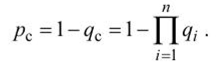
The unreliability of an element (the average probability of a failure condition) is determined by the average probability of its total simply due to a forced shutdown due to damage and deliberate shutdowns for prevention. [12]
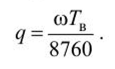
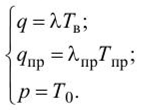
Probability of downtime
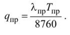
Probability of intentional shutdown
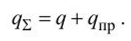
Average probability of a failure condition (total)
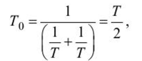
The probability of a working state (availability factor) is determined by the formula
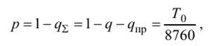
where t 0 is the uptime of the element.
If the times tv, tpr, tr are measured in years, then
The above reliability indicators can also characterize the system as a whole. For most of the tasks related to the technical and economic assessment of the reliability of power supply systems, there is no need to consider reliability indicators over short time intervals. Therefore, the initial states of the elements can be ignored. In addition, the use of queuing theory methods (Markov processes) for these purposes encounters great computational difficulties if the system has a large number of recoverable elements and an arbitrary switching scheme. Therefore, when calculating reliability indicators in time intervals equal to a season, a year, you can use simpler probabilistic models based on the average values of the probabilities of the state of the elements[11].
2.2 Probabilities of failure and non-failure state of circuits with serial connection of elements
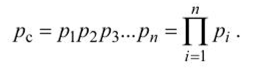
If the design scheme for reliability consists of n series-connected elements, then it will be in working order when all n elements are in working order. A complex event - the work of all elements of the circuit is obtained as a result of combining events - the work of each element. Applying the theorem of multiplication of the probabilities of independent events, we obtain the probability of the operating state of such a circuit:
The failure state probability is defined as the probability of an event opposite to the operating state
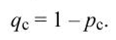
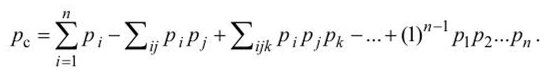
In practical calculations, another method is usually used to determine the probabilities of element failure states. In this method, the circuit failure probability is defined as the probability of failure of at least one element. The probability of this event is determined using the formula for the probabilities of the sum of joint events:
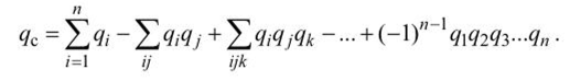
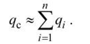
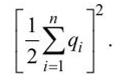
The elements of electrical systems are characterized by relations at which qi << 1. Therefore, when determining the probability of a failure state of a system of n series-connected elements, the second, third, etc. terms on the right side of the last equality can be neglected as numbers of a higher order of smallness. Therefore, in practical calculations, the formula is used
In this case, the calculation error does not exceed the value
If the circuit of series-connected elements in terms of reliability corresponds to the circuit diagram of the connection of elements, then given that in real conditions preventive maintenance of elements of a series circuit is carried out simultaneously, the probability of circuit downtime should be determined by the formula
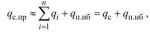
where g/p.nb is the largest of the probabilities of intentionally disconnecting a circuit of n elements. [11]
When elements are connected in series in a reliability logic circuit, the probabilities of failure-free operation of elements are multiplied, therefore, with an exponential distribution law, the probability of failure-free operation of the circuit:
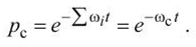
If we consider a time interval equal to 1 year (/ = 1), then
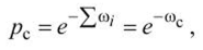
from here
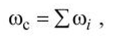
those. when connected in series, the parameters of the failure flows are added.
Therefore, the greater the number of elements n connected in series in the reliability logic circuit, the greater the value of the system failure flow parameter and the less the probability of its reliable operation.
The mean time between failures, or time between failures, for such an n-element circuit is [15].
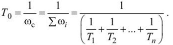
For a circuit of two series-connected elements with the same failure flow parameters, with o =
those. with an increase in the number of elements, the operating time of the system decreases.
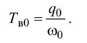
If the probability of forced downtime and the failure rate parameter coc are known, it is possible to determine the average time for one restoration (emergency repair) of the system in fractions of a year:
2.3 Probabilities of failure and non-failure state of circuits with parallel connection of elements
Consider a circuit consisting of n elements connected in parallel, provided that the failures of each element are independent and the throughput of each is sufficient to provide all the power required by the consumer. Such a system will be operational provided that at least one element is working.
The probability of the operating state of the circuit is determined using the formula for the sum of the probabilities of joint independent events - the operation of each element.
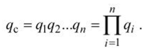
Determining the probability of the system operation using this formula is very laborious, since it is necessary to calculate and add (2n - 1) terms. As a result, all terms should be taken into account, since their values are close to unity. Therefore, the probability of reliable operation of the system is more simply determined by the probabilities of the failure state of the elements. The system will be in a failure state provided that all elements fail. The probability of a failure condition is determined using the formula for the product (combination) of independent events - failures of each element of the system: [11]
The probability of the operating state of such a system is defined as the probability of the opposite event (system failure)
Let us consider a method for determining the probability of a failure state in a system consisting of n parallel-connected elements, taking into account the deliberate shutdowns of individual elements. Moreover, no more than one element can be deliberately disabled at the same time, and during disaster recovery, deliberate shutdowns are not performed. To determine the probability of a failure state of such a system, it is advisable to consider, in addition to the probability of a complex event - failures of all elements, also the probability of n hypotheses, in each of which the probability of system failure is considered when one element is deliberately turned off. Since the hypotheses are independent due to the independence of the elements, the probability of a failure state of the system is determined as the sum of the probabilities of failure states for each hypothesis.
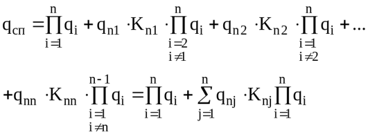
When determining the probabilities of failure states for each hypothesis, a reduction factor Кпj < 1 is introduced, taking into account the decrease in the probability of the accident of the remaining part of the circuit superimposing on the deliberate shutdown of the j-th element. Usually, the duration of intentional disconnection of elements of electrical systems is relatively short, therefore, when determining the probability of an emergency failure of the remaining part of the circuit during this time, it is necessary to take into account the initial states of the elements and model the processes of failures and recovery by a Markov process. It is expedient to represent the rest of the circuit for each hypothesis as one equivalent element with the properties of the simplest flow of failures and restorations [11].
With the complication of the relationship between the elements, the design scheme for reliability without the use of special techniques cannot be reduced to a scheme with a series-parallel or parallel-series connection of elements. For example, for a bridge circuit or a circuit with a large number of cross-links, the rules for converting series-to-parallel or parallel-to-series reliability circuits do not apply.
1) a method for analyzing the probabilities of system states with an analysis of the parameters of modes in each state (this method determines the parameters for partial system failures);
2) a method using the total probability formula and a factorization method based on it;
3) a method using structural representations of the circuit, i.e. replacing a complex circuit with equivalent serial-parallel or parallel-serial connections of elements with respect to key points [12].
Сonclusions
1. Carrying out the reform of the energy industry puts forward the problem of ensuring the reliability of electricity supply among the priorities of public administration. In recent years, the natural process of equipment aging has begun to outstrip the pace of renewal of electrical networks, which has led to a decrease in the reliability of power supply to consumers.
2. Reliability management in the course of planning, design, construction, in the process of maintenance and repair needs methodological support at the modern scientific level and justification of the technical means used.
3. Analysis of statistical data on technological failures in electrical networks of power systems indicates the need to develop a strategy that will improve the technical condition of the equipment and increase the reliability of power supply to consumers [15].
List of sources
- Анищенко В. А., Колосова И. В. Основы надежности систем электроснабжения. Мн. : БНТУ, 2007 г.
- Гутов А. И. Электроснабжение промышленных и сельскохозяйственных предприятий. Ползуновский альманах. № 1. 2004
- Танкович Т.И. Надёжность электроснабжения ПИ СФУ, 4 курс, Электроснабжение 2009г. , 119 стр.
- Волков Н.Г. Надежность электроснабжения Учеб. Пособие. Том. политех. ун-т. – Томск, 2003.– 140 с.
- Воропай Н.И. Надежность систем электроснабжения. Новосибирск: Наука, 2006. – 205 с.
- Хорольский В.Я., Таранов М.А. Надежность электроснабжения. Ростов-на-Дону: «Терра Принт», 2007. — 128
- Васильева Т. Н. Надежность электрооборудования и систем электроснабжения. — М.: Горячая линия — Телеком, 2015. — 152 с.: ил.
- Воропай Н. И. и др. Концепция обеспечения надежности в электроэнергетике. — М.: ООО Изд. «Энергия», 2013.
- Довлатов И.М. Комплексная оценка применения кабельных, воздушных и самонесущих линий электропередач в районах с малой плотностью нагрузок // Инновации в сельском хозяйстве: электронный журнал ВИЭСХ. Материалы 5-й Межд. научнотехн. конф. молодых ученых. – 2014
- Герасименко А.А., Федин В.Т. Передача и распределение электрической энергии. Ростов-на-Дону: Феникс, 2008. – 716 с.
- Лещинская Т.Б., Князев В.В. Многокритериальная оценка технико-экономического состояния распределительных электрических сетей. М.: ФГОУ ВПО МГАУ, 2006. – 100 с.
- Подобедов П.Н. Методика оценки предложенных конструкций изоляторов и проводов по многокритериальной модели // Инновации в сельском хозяйстве: электронный журнал ВИЭСХ. Материалы 5-й Межд. Научно техн. конф. молодых ученых. 2014
- Кудряшев Г.С., Третьяков А.Н., Шпак О.Н. Влияние потерь электроэнергии на надежность электрооборудования в сельской электросети 0,4 кВ // Электротехнологии и электрооборудование в АПК. 2021. Т. 68. N1(42). С. 34-38. DOI 10.22314/2658-4859-2021-68-1-34-38
- M.Ratier, O.Vanackere, E. Chabat-Courrede, J.-L. Lapeyre. Propriete mecaniques, viellissement et C.N.D. de supports en bois. Electrcte de France. Direction des etudes et Recherches, epure 45. Janvier 1995. pp 3-16
- А.П. Васильев, А.Г. Турлов., Средства обеспечения надежности электроснабжения потребителей. Проблемы энергетики, 2006, № 3-4 с19-35.