
Abstract
Содержание
- Introduction
- 1. The current state and ways to improve the diagnosis of asynchronous motors
- 1.1 Fault Analysis of Induction Motors
- 1.2 Overview of methods and devices for diagnosing faults in asynchronous motors
- 2. Electromechanical characteristics of asynchronous motors in case of stator winding failures
- References
Introduction
Relevance of the topic. Asynchronous motors (AM) are one of the most common electrical machines. About two thirds of the generated electrical energy is consumed by electric motors, and the share of AM is about 95% of their amount [1]. The high damage rate of asynchronous machines causes significant losses. Every year, 29-30% of engines fail in the mining industry, 20% in the machine-building industry, and 13% in the metallurgical industry [2]. Electric motors account for 25-30% of the total number of damage to electrical equipment [3].Common causes of AM failure are stator winding failures - breaks and interturn short circuits. Timely detection of stator winding failures helps to prevent more serious damage to the motor, reduce recovery time, reduce maintenance costs and losses from unscheduled downtime, and increase the efficiency of motors and production mechanisms. Thus, further studies of the features of the operating modes of AM in the presence of malfunctions for the development of methods and diagnostic tools are relevant.
1. The current state and ways to improve the diagnosis of asynchronous motors
1.1 Fault analysis of induction motors
During the operation of asynchronous motors, malfunctions of the stator windings occur (breaks, interturn short circuits, short circuits to the housing, interphase short circuits, malfunctions of the stator active steel, etc.), the rotor (breaks in the bars of squirrel-cage rotors, damage to the windings of phase rotors, etc.), mechanical failures (wear and tear of bearings, rotor beating, rotor rubbing against the stator, etc.).
Researchers note a high percentage of failures associated with malfunctions of the stator windings. So in [4] it is indicated that for electric motors of the A, A2, AO, AO2, AOL, AOL2 series and their modifications, the proportion of stator winding failures is 71-100%. Other researchers also note the high damage to stator windings. In [5], it is indicated that 85% of domestically produced motors fail due to insulation failures in the stator winding. Abroad also note a significant percentage of failures for this reason. So 30-40% of the total number of failed AMs in the USA fail due to the destruction of the insulating materials of the stator winding [6]. A similar picture in the distribution of AM failures takes place in other countries [7].
Researchers note some features of the operating modes of AM with malfunctions of the stator windings [8].
The most thoroughly investigated malfunction is phase failure. It is known that when a phase breaks, the starting torque of the AM is zero, and when the engine is turned on, a short circuit occurs, the currents in the healthy phase windings are many times higher than the nominal ones, which leads to intense overheating and rapid failure of insulating materials under the influence of high temperatures and their gradients. . If a break occurs during operation, the motor can continue to rotate, however, the currents in the operating phase windings exceed the nominal values, which leads to overheating of the insulating materials of the windings and the failure of the motor [8]. The literature contains the results of studies of this mode of operation, however, the issues of determining the magnitude of the currents and the temperature state of the machine with a rotating and stationary rotor require additional consideration.
In some cases, the stator windings are connected according to schemes with parallel branches in each phase winding. Noteworthy is the operation of the engine with a break in one of the branches connected in parallel. It is known [9] that the current of healthy branches of the damaged phase can significantly exceed the nominal value, which leads to local overheating. At the same time, the phase currents differ in magnitude from the nominal ones not so significantly, which complicates the detection of a malfunction. The features of the AM operation mode are covered in [9], however, in order to identify diagnostic signs for the development of methods and tools for the timely detection of a malfunction, it is advisable to conduct more detailed studies of the electromechanical and thermal processes of the AM.
Of great interest are the features of the operation of AM in the presence of interturn short circuits. It is known that in the early stages of development, interturn short circuits do not have a noticeable effect on the performance of the machine [10]. At the same time, short-circuit currents flow in short-circuited turns, which can lead to a quick failure of the windings [11].
In general, as a result of any malfunction of the stator windings, an asymmetric motor operation occurs, which leads to a redistribution of currents in the phase windings. Moreover, in individual phases (parallel phase branches, short-circuited turns, etc.), the current values significantly exceed the nominal values, which causes increased heat losses and the temperature of the insulating materials exceeding the maximum allowable values.
Thermal loads are the main reason for the decrease in the electrical strength of insulation [12]. The characteristics of thermal overloads are the magnitude of the temperature, the duration of its impact and the rate of increase (gradient). GOST 8865-70 provides for seven classes of heat resistance of insulating materials. Each class corresponds to the permissible temperature at which the insulation of an electrical machine retains its mechanical and electrical properties during the estimated service life (10,000 - 20,000 hours) [1]. If the temperature exceeds the permissible value, the insulation service life is reduced due to "thermal aging". The service life of the insulation at a constant temperature throughout the entire operation time for the known nominal service life of the insulation DH and the allowable temperature is determined by the Van't Hoff and Arrhenius equation [13]:
(1.1)

where Ea is the activation energy for a given type of insulating material;
R - universal gas constant;
D - estimated service life.
In table. 1.1 shows the calculation of the reduction in the service life of class F insulating material as a function of τ/τH in relative units [14].
Table 1.1 - Dependence of the reduction in service life of insulating materials D/DH class F on the temperature ratio τ/τH in relative units.
τ/τH 1 1,1 1,2 1,3 1,4 D/DH 1 0,48 0,25 0,15 0,1 From the table. 1.1 it follows that a slight excess of the permissible temperature value causes a noticeable reduction in the service life. Thus, the operation of AM with a constant temperature exceeding the nominal value by 10% leads to a reduction in the service life of insulating materials by more than two times, which indicates the need to control the temperature of the windings.
1.2 Overview of methods and devices for diagnosing faults in asynchronous motors
In order to analyze diagnostic methods, it is advisable to classify existing approaches. On fig. Table 1.1 shows the classification of diagnostic methods according to the parameters used [15]. The analysis of diagnostic methods and tools is carried out further in accordance with the above classification.
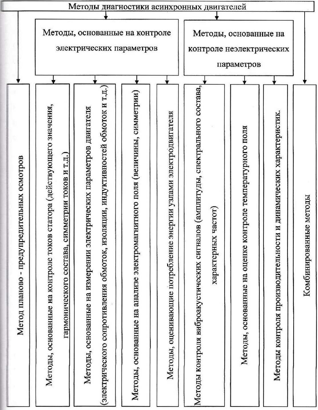
Figure 1.1 - Classification of diagnostic methods by diagnostic parameters.
Historically, the first approach to AM maintenance is the method of scheduled inspections, the essence of which is periodic disassembly and visual assessment of the wear of the AM structural elements. If necessary, replacement of parts that have worked out the average uptime is carried out. The frequency of inspections and the frequency of replacement of components are determined based on the statistical processing of operational information obtained from the observation of a large number of samples of these sizes, serial production and in these operating conditions. The considered approach has the following advantages:
- periodically cleaned of dust and dirt;
- visually assesses signs that are often impossible to detect by other methods: discoloration of insulating materials, oil contamination, etc.;
- the ability to control engines of any type;
- low costs for diagnostic equipment.
However, the method under consideration also has certain disadvantages:
- high cost of maintenance associated with the need to use additional personnel, stop equipment and carry out inspections often unnecessarily;
- replacement of nodes is often premature, at the same time, the occurrence of an unscheduled failure is not excluded (under the influence of abnormal operating modes, due to low quality of components, etc.);
- periodic disassembly of the machine reduces its reliability.
Maintenance of AM by the method of scheduled inspections has not lost its relevance when using a large number of low-responsibility engines due to the minimal cost of diagnostic equipment. However, there is now increasing interest in state of the art maintenance. A feature of this method is the inspection and repair of the machine only if necessary. Condition-based maintenance means are technical diagnostic systems that perform continuous or periodic diagnostic measurements at the required interval in automatic mode. Significant attention to maintenance based on the current state is caused by the following advantages of the method [16]:
- malfunctions are fixed, as a rule, until a complete failure, in the early stages of development, which makes it possible to reduce the number of sudden failures by dozens of times, and the costs of unscheduled downtime by several times;
- labor costs for assessing the state are minimal, most operations are performed automatically;
- it is possible to take into account sudden changes in external factors of a random nature;
- It is possible to diagnose hard-to-reach engines, there is no need for frequent unreasonable disassembly of machines.
According to the U.S. Energy Industry Research Institute [17], the unit maintenance cost of electric motors is $18 per horsepower (hp) - running to failure; $13 per hp - when servicing according to the regulations; $9 per hp - when servicing according to the current state. Thus, the expediency of using these systems is economically justified.
Currently, there are many approaches to the construction of automatic systems for the technical diagnosis of BP malfunctions. A significant number of diagnostic systems use data on the instantaneous values of stator currents. This is due to the high information content and availability of signals, the possibility of diagnosing during operation.
The determination of the technical condition of the electric motor and the presence of defects in the stator windings, rotor rods, uneven air gap, faulty gearboxes, etc., are obtained by the authors of works [18, 19] using harmonic analysis of the stator current. The manifestations of the presence of faults are the appearance of pronounced higher harmonic components of the current, characteristic of each indicated fault. There are many devices that perform harmonic analysis of phase currents and present information in a user-friendly form. A spectrum analyzer (Microlog data collector, EPRI Monitoring and Diagnostic Center at Eddystone, PA, etc.) can be used as such a device.
2. Electromechanical characteristics of asynchronous motors in case of stator winding failures
Phase breaks, parallel branches of phase windings and interturn short circuits lead to the occurrence of longitudinal asymmetry, presented in general form in fig. 2.1, a. Using the compensation theorem, the source of asymmetry can be replaced by an equivalent system of asymmetric voltages, which is then represented as a system of symmetrical components: zero (U(0) A, U(0) B, U(0)C), straight (U(1) A, U(1)B, U(1)C) and reverse (U (2)A, U(2)B, U(2) C) (Fig. 2.1, b).
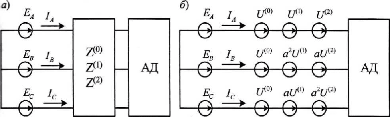
Figure 2.1 - Calculation scheme for AM with phase failure according to the method of symmetrical components.
Calculation and analysis of unknown currents fig. 2.1, b is possible with known input resistances of AM for all sequences. To calculate the input resistance of AM, it is advisable to use a T-shaped equivalent circuit for direct (Fig. 2.2, a) and reverse (Fig. 2.2, b) sequences [20].
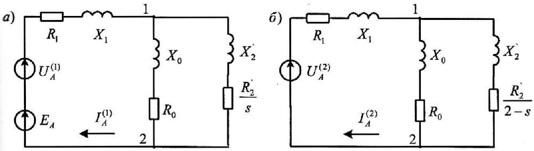
Figure 2.2 - T-shaped equivalent circuit of phase A (with a break) of an asynchronous machine:
a) for direct sequence; b) for the reverse sequence.In the equivalent circuits of fig. 2.2 notation accepted:
R1 and X1 - active resistance of the stator winding and inductive leakage resistance, respectively;
R0 - active resistance, taking into account steel losses;
X0 - inductance of the magnetization circuit;
X'2, R'2 - leakage inductance and rotor active resistance reduced to the stator respectively;
s - slide;
I(1)A, I(2)A - phase winding currents of positive and negative sequences, respectively;
U(1)A, U(2)A - positive and negative sequence voltages introduced at the break.
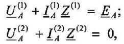
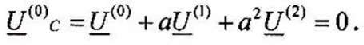
For design schemes fig. 2.2 form equations (2.1).
(2.1)
where
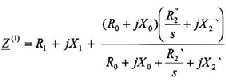 - positive sequence AM resistance;
where
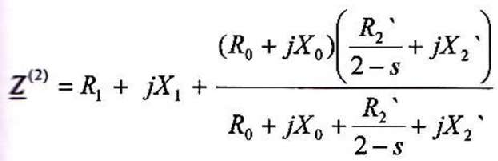 are negative sequence AM resistances.
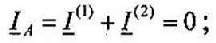
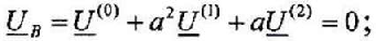
Equations (2.1) are supplemented by three equations describing the presence of a fault. So, for a phase break, these equations are compiled from the conditions IA=0, UB= 0, UC=0 and have the form:
(2.2)
(2.3)
(2.4)
As a result, equations (2.1 - 2.4) form a system of five equations with five unknowns: U(1), U(2), U(0), I(1), I(2) [21].
From the analysis of dependencies (2.1) it follows that the calculation of the input resistances of AM is performed for a given slip. The amount of motor slip depends on the moment of resistance. The following algorithm was used to determine the slip corresponding to an arbitrary moment of resistance.
- The amount of slip s is assumed to be zero.
- For a given slip, the currents and moments of the positive and negative sequences (2.5 - 2.12) and the total electromagnetic moment were calculated M∑ = M(1) - M(2).
- The total electromagnetic moment was compared with the moment of resistance. If the resulting electromagnetic moment of the motor is greater than the moment Mi, the slip value changes by a step Δs: si+1=si + Δs, the calculation is repeated from point 2. In the calculations of sliding at a moment close to the nominal, Δs is assumed to be 0.001, which provided a calculation error of no more than 5%.
(2.5)
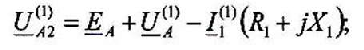
(2.6)
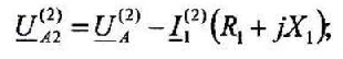
(2.7)
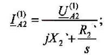
(2.8)
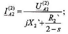
(2.9)
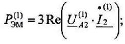
(2.10)
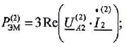
(2.11)
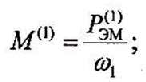
(2.12)
where U(1)A2, U(2)A2 - voltage on section 1-2 of phase A substitution schemes;
P(1)ЭМ, P(2)ЭМ - full power on the motor shaft of the forward and reverse sequence, respectively;
ω1, ω2 - angular rotation speed for forward and reverse sequence, respectively.
References
- Справочник по электрическим машинам: в 2т. / [под ред. Копылова И.П., Клокова Б.К.]. - М.: Энергоатомиздат, 1988. Т. 1.- 1988.-456 с.
- Родькин, Д. И. К определению послеремонтной работоспособности асинхронных двигателей / Д.И. Родькин, А.П. Черный // Вiсник Кременчуцького Державного політехнiчного Університета. - 2001. - №2. - С. 40-47.
- Федоров, М. М. Особенности теплового состояния асинхронных двигателей при несимметричном питающем напряжении / М. М. Федоров, О.Г. Пинчук // Вісник Кременчуцького Державного полiтехнiчного Унiверситета. - 2004. - №2. - С. 122 - 125.
- Надежность асинхронных электродвигателей / [Б.Н. Ванеев В.Д. Главный, В.М. Гостищев, Л.И. Сердюк]; под ред. Б.Н. Ванеева. - К.: Техника, 1983. - 143 с.
- Родькин, Д.И. Системы динамического нагружения и диагностики электродвигателей при послеремонтных испытаниях / Д.И. Родькин. - М: Недра, 1992. - 190 с.
- Kliman, G. В. A new approach to on-line fault detection in ac motors / [G. B. Kliman, W. J. Premerlani, R. A. Koegl and D. Hoeweler], IEEE-IAS Annual Meeting Confemce. - San Diego, CA. - 1996. - P. 687-693.
- Arthur Neil. Supply Invariant Induction Machine Condition Monitoring / Neil Arthur, Jim Penman // Proc. International Conf, on Electrical Machines and Drives. - Cam-bridge, 1997. - P. 341-345.
- Трещев, И.И. Электромеханические процессы в машинах переменного тока / И.И. Трещев. - Л.: Энергия, 1980. - 344 с.
- Федоров, М. М. Тепловое состояние электродвигателей переменного тока при об-рывах параллельных ветвей статорных обмоток / М.М. Федоров, В.Ф. Денник // Сборник научных трудов ДонгНТУ. Серия «Электротехника и энергетика». - № 17. - Донецк, ДонГТУ, 2000. - С. 87-91.
- Bonnett, А. Н. Cause and analysis of stator and rotor failures in three-phase squirrel-cage induction motors / A.H. Bonnett, G.C. Soukup // IEEE Transactions on Industry Applications. - USA, 1992. - № 28. - P. 921-937.
- Diagnosis of stator winding inter-turn shorts in induction motors fed by PWM-Inverter drive systems using a time-series data mining technique / ChiaChou Yeh, Richard J. Povinelli, Behrooz Mirafzal, Nabeel A.O. Demerdash // International Conference on Power System Technology. - Singapore, 2004. - P. 854-860.
- Казарновский, Д.M. Испытание электроизоляционных материалов и изделий / Д.М. Казарновский, В.М. Тареев. - Л.: Энергия, 1980.-213 с.
- Ермолин, Н. П. Надежность электрических мащин / Н.П. Ермолин, И.П. Жерихин. - Л.: Энергия, 1976. - 247 с.
- Федоров, М.М. К вопросу построения систем диагностики неисправностей асинхронных электродвигателей / М.М. Федоров, А.А. Ткаченко // Электротехника и электромеханика. - Харьков: НТУ «ХПИ», 2006. - №2. - С. 59-61.
- Панкратов, А.И. Проблемы диагностики асинхронных машин / А.И. Панкратов, А.А. Ткаченко, Н.В. Ивченков //Вестник Национального технического университета «Харьковский политехнический институт». - Харьков . - 2004. - № 43. - С. 182-183.
- Барков, А.В. Интеллектуальные системы мониторинга и диагностики машин по вибрации / А.В. Барков, Н.А. Барков // Труды Петербургского энергетического института повышения квалификации Минтопэнерго Российской Федерации и Института вибрации США (Vibration Institute, USA). - Санкт-Петербург, 1999. - № 9. - С. 102-105.
- Барков, А.В. Сервис технологических машин. Технология обслуживания по фактическому состоянию. [Электронный ресурс] / А.В. Барков, П.П. Якобсон. - Название с заголовка страницы. - Режим доступа к ресурсу: littp://vdmk.com/information/tofs.htm.
- Thomson, W.T. Current signature analysis to detect induction motor faults / W.T. Thomson, Mark Fenger // IEEE Industry Applications Magazine. - 2001. -№ 7. -P. 26-34.
- Kliman, G. B. Induction motor fault detection via passive current monitoring / G. B. Kliman, J. Stein // Proc Int. Conf. MIT. - Boston, USA, 1990. - P. 13-17.
- Копылов, И. П. Электрические машины / И. П. Копылов. - М.: «Высшая школа», 2000. - 607 с.
- Федоров, М. М. Режимы работы асинхронных электродвигателей при неисправностях обмотки статора / М.М. Федоров, О. И. Толочко, А.А. Ткаченко // Сборник научных трудов УкрНИИВЭ: Взрывозащищенное электрооборудование. - Донецк: ООО «Юго-Восток, Лтд», 2006. - С. 320 - 325