
Summary on the topic of graduation work
Content
- Introduction
- 1. Relevance of the topic
- 2. Purpose and objectives of the study
- 3. Scheme and principle of operation of thermal power plants and thermal power plants
- 4. General concepts of regenerative rotating air heater
- 5. Scientific novelty
- 6. The existing method of cleaning the regenerative air heater from ash
- 7. Hydro-pulse method of cleaning from ash of regenerative air heater
- Conclusions
- References
Introduction
In the modern world, an important industry is energy, which determines the progress of social production. In all industrialized countries, the pace of energy development outpaced the pace of development of other industries. Energy is a key industry for many countries of the world in economic, social and political terms. In this regard, the fuel and energy complex (fuel and energy complex) is under the special supervision of the state and is quite strictly regulated, regardless of the forms of ownership of energy companies. The level of both national security in general and its economic component depends on the state of the fuel and energy complex. This determines the special attention on the part of public administration bodies to the issues of ensuring energy security.
It is already impossible to imagine life without electric energy. The electric power industry has invaded all spheres of human activity: industry and agriculture, science and space, and is widely used in everyday life.
1. Relevance of the topic
Electricity is generated in various ways, the main of which are: thermal power (using fossil fuels); hydropower (using water flow energy); nuclear power (using the energy of a nuclear fission chain reaction of uranium or plutonium); alternative energy, including such areas as: wind energy, solar energy.
In Russia, electricity is produced at three main types of power plants: thermal (TPP), hydraulic (HPP) and nuclear (NPP). In terms of electricity production, Russia ranks fourth in the world after the United States, Japan and China.
Most of the electricity produced in the Russian Federation is generated at thermal power plants [1]. Thus, electricity generation in the Russian Federation at the end of 2021 among its producers was distributed as follows:
1. Heating stations: 638.0 TWh
2. Hydropower: 197.0 TWh
3. Nuclear power plants: 205.0 TWh
4. Wind power: 0.10 TWh
5. Solar energy: 0.12 TWh.
2. Purpose and objectives of the study
The aim of the work is to study the problem of regenerative air heater, increase the efficiency and efficiency of thermal power plants in Donetsk and Lugansk People's Republics, namely Starobeshevskaya and Lugansk thermal power plants. Research objectives:
1. Prevention of fuel overspending by power plants.
2. Cleaning of thermal power equipment from ash deposits.
3. Scheme and principle of operation of thermal power plants and thermal power plants
The thermal power plant – TPP is designed exclusively for the production of electricity.
Thermal power plant – CHP is a type of thermal power plant. In addition to generating electricity, it supplies hot water to the central heating system and for domestic needs [2].
The scheme of operation of the CHP is quite simple. Fuel and heated oxidizer air enter the furnace at the same time. The most common fuel at Starobeshevskaya and Lugansk CHP plants is crushed coal. The heat from the combustion of coal dust turns the water entering the boiler into steam, which is then pressurized to the steam turbine. A powerful stream of steam makes it rotate, driving the rotor of the generator, which converts mechanical energy into electrical energy.
Further, the steam, which has already significantly lost its initial parameters – temperature and pressure – enters the condenser, where after a cold "water shower" it becomes water again. Then the condensate pump pumps it into regenerative heaters and then into the deaerator. There, the water is freed from gases – oxygen and CO2, which can cause corrosion. After that, the water is reheated from steam and fed back into the boiler. The scheme of operation of the thermal power plant is shown in Figure 1.
Picture 1 – The thermal power plant – TPP is designed exclusively for the production of electricity.
4. General concepts of regenerative rotating air heater
A regenerative air heater (RVP) is a type of air heater where the exhaust gases first give heat to metal plates, which in turn rotate and give heat to the air when they are in an air shaft during rotation [3]. The scheme of the regenerative rotating air heater is shown in Figure 2.
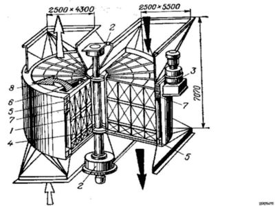
Picture 2 – Regenerative air heater (RVP)
1 – rotor shaft; 2 – bearings; 3 – electric motor; 4 – gaskets; 5 – outer casing; 6, 7 – radial and peripheral seals; 8 – air leakage through seals
The air heater is a mandatory element of a modern steam boiler. Its value increases with the increase in the power of the unit. This is due to the fact that the temperature of the flue gases behind the economizer is significant (350-400 ° C), and the use of this heat in the air heater reduces the temperature of the exhaust gases to 120-160 ° C. It is also important that air heating increases the efficiency of the boiler [4].
Flue gases leaving the boiler, passing through the plates (packing) of the rotating rotor, heat them and go into the chimney. As a result of rotation of the rotor, the heated plates move to the diametrically opposite side of the air heater and fall into the area of the air ducts. Passing through the heated plates, the air injected by the blast fans heats up, and the plates cool down.
By applying heated air during the operation of the boiler gorenje processes are accelerated, heat loss with the outgoing gases is reduced.
5. Scientific novelty
When burning fuel, deposits consisting of small ash particles form on the heating surface of regenerative air heaters and lead to rapid clogging of the passage channels.
Currently existing cleaning methods require the shutdown of power units. These methods are time-consuming and ineffective. Therefore, there is a gradual contamination of regenerative air heaters and, as a result, the temperature of the primary air supplied for fuel combustion decreases, which leads to a loss of the operating power of the units. So, a 300 MW unit with a heavily polluted packing operates at a power 12-15% below nominal, that is, it does not supply about 40,000 kWh of energy per day to the system.
Currently, the cleaning of the RVP is carried out according to the technology of the Boiler cleaning plant by continuous jets of water flowing at a pressure of 20 MPa through nozzles with a diameter of 2 mm. To form such a jet, the ATYUMAT installations of the VOMA company (Germany) are used [5-7].
The purpose of this work is to develop a device for cleaning the RVP with thin pulsating jets of water. This will allow you to replace expensive imported equipment and reduce the time required for cleaning.
Studies conducted in the second half of the last century both in our country and abroad have shown the effectiveness of a pulsating jet compared to stationary ones. DonNTU employees also took part in these studies. The result of the research was the creation of hydraulic pulsators converting a stationary flow with a pressure of 4-6 MPa into a pulse flow with an amplitude of up to 20 MPa and generators converting a stationary flow with a pressure of 30 – 32 MPa into a pulse of the same pressure. The difference between these devices consisted in the amount of working fluid supplied to them. If for the normal operation of the first, the supplied amount of working fluid was 150-200 m3 / hour, then for the second 3 – 6 m3 / hour. The power consumption of the first is 1250 kW, the second is 55 kW. Since the energy in the pulse of both the hydraulic pulsator and the generator is almost the same – 500-700 kW, the amount of energy consumed was decisive in choosing a device to ensure effective cleaning of the air heater packing.
To supply the pulse flow to the cleaning zone, a connecting pipeline and a device distributing this flow over the surface to be cleaned are required.
In order to optimize the ratio of the diameters of the flowing part of the connecting pipeline (the jet-forming trunk) and the diameter of the equivalent nozzle, theoretical studies of wave processes occurring in the first one are presented.
Practical significance of the results obtained
Based on these studies, the supply pipeline, the executive body and hydraulic cylinders were calculated and designed to ensure its movement during the removal of ash deposits from the surface of the blades of the regenerative air heater.
6. The existing method of cleaning the regenerative air heater from ash
Ash deposits on the surface of the regenerative air heater are very difficult to remove. These deposits are very difficult to remove. Even frequent processing does not ensure reliable cleaning of the RVP and does not always prevent the growth of aerodynamic drag.
Mechanical cleaning methods are simpler, but inefficient. They are recommended to be used in combination with other methods for cleaning accessible areas of equipment. This method of cleaning is carried out manually with the help of various scrapers.
The hydraulic cleaning method is the removal of ash from the surface of metal plates by a stationary jet of water under high pressure. To facilitate the churning of ash, water jets from the nozzles are directed at an angle against the movement of the plates.
Since the main part of the deposits formed on the plates easily dissolves in water, the most effective way to clean the RVPs was to wash them with water. This method has become widespread both in foreign and domestic energy [8-9].
7. Hydro-pulse method of cleaning from ash of regenerative air heater
In recent years, an attempt has been made at a number of power boilers to use pulse cleaning to remove ash deposits from regenerative air heaters. Numerous studies prove the advantages of a hydro-pulse jet compared to a stationary jet. This was confirmed with the help of a hydraulic pulsator (developed by DonNTU) for cleaning a regenerative air heater at the Starobeshevskaya TPP [10-11]. Prior to the use of the hydraulic pulsator, the ash cleaning of the regenerative air heater was carried out by a stationary jet. The plant was powered by a high-pressure pump, the power consumption of which was 1250 kW. The pulse jet generator consumes 55 kW of power, which significantly reduces costs. The advantage of this cleaning method is lower energy consumption compared to other cleaning methods. The hydro-pulse cleaning method also has other advantages such as: fire and explosion safety, preservation of the shape and roughness of the treated surface. The hydraulic circuit of the pulse jet generator is shown in Figure 3
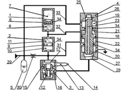
Picture 3 – Hydraulic diagram of the pulse jet generator
The pulse jet generator consists of a hydropneumoaccumulator (HPA) 1, a storage unit 2, a main valve 3, a control valve 4, an additional HPA 5, and an executive body.
The hydropneumoaccumulator 1 accumulates energy, transfers it to the working flow at the moment of the pulse.
The accumulator 2 is designed to set the volume of the shot and generate a signal for the actuation of the control valve.
The main valve 3 is used for periodic connection of the GIS output to the executive body of the installation.
The executive body 13 is designed to form and direct the jet to the desired point of the destroyed array.
The control valve 4 is used to monitor the state of the drive and to switch the main valve.
An additional HPA 5 serves to protect the main line from pressure fluctuations created in the system.
Conclusions
When writing the abstract, the methods of cleaning the regenerative air heater from ash were considered, the analysis of existing methods was carried out, the use of a pulse jet generator for these purposes was proposed.
The work is aimed at using a pulse jet generator for rational cleaning of the air heater and ensuring effective removal of ash from the surface of metal plates.
List of literature
- Kolomiets V. S., Zuikov A. L. optimization of barrel parameters for pulse jet formation. - Collection of scientific papers Bulletin of the Donbass State Machine-Building Academy. - 2005, №1.
- Semenko A. N., Sherstyuk Yu. V.Gidropushki for solving ecological problems.
- Nedopekin F. V., Nechepaev V. G./ edited by Prof., doctor of technical sciences A. N. Semko / pulsed jets of high-speed liquid and their application. Donetsk: Donntu publ., 2014, 370s.
- Kolomiets V. S., Zuikov A. L. experimental studies of pulse jet formation modes. - Scientific works of Donntu. Issue 14 (127), mining and electromechanical series. Donetsk: Donntu publ., 2007, 306 p. (in Russian).
- Kolomiets V. S. Determination of the rational frequency of the jet of a hydraulic pulse installation for mining operations / O. A. Gemmerling. — Naukovi pratsi DonNTU. Vip. 18(172), series girnichno-elektromekhanichna. — Donetsk: DVNZ DonNTU, 2010. — 282 p.
- Rizun A.R., Shvets I.S., Golen Yu.V. Electrohydroimpulse technology and equipment for pipe cleaning/ 2003 pp. 67-69
- Scientific Library [Электронный ресурс]
- Energy reference book [Электронный ресурс]
- Patent search [Электронный ресурс]. Mechanics. Lighting. Heating. Engines.
- Patent search [Электронный ресурс]. Hydraulic and pneumatic actuators; general purpose pneumohydraulic systems.