
Abstract on the topic of graduation work
Content
- Introduction
- 1. Relevance of the topic
- 2. Purpose and objectives of the study
- 3. Scheme and principle of operation of a water jet pump
- 3.1 Jet pumps: device and principle of operation
- 3.2 Design of the jet pump
- 4. Existing ways to control a water jet pump
- 4.1 Throttling the pump flow
- 4.2 Pump flow control by bypass
- 4.1 Adjusting the pump flow by changing the speed
- Findings
- List of sources
Introduction
The first use of a jet pump dates back to the 19th century. At that time, such equipment was used in laboratories for pumping water and air out of flasks. Then jet pumps were used in the mining industry to pump water out of mines.
In domestic use, a jet pump is often used in water wells, as well as for pumping sewage with sand and silt.
1. Relevance of the topic
Modern modifications of jet pumps are divided into three categories
Ejector - used to pump liquid. The mechanism of operation is the suction of liquid substances.
Injector - works on the principle of injection of liquid substances. The working medium is steam.
Elevator - used to lower the coolant temperature by mixing with the working fluid [2].
Only one operating point corresponds to this characteristic of the pump and pumping unit. Meanwhile, the required supply may vary. In order to change the operating mode of the pump, it is necessary to change the characteristics of the pump or pumping unit. This change in characteristics to provide the required feed is called regulation. The regulation of centrifugal and small axial pumps can be carried out either using a control valve (the characteristic of the pumping unit changes) or by changing the speed (the characteristic of the pump changes). Sometimes small axial flow pumps are controlled by bypassing part of the flow from the pressure pipe to the suction pipe. The operation of the installation with medium and large axial flow pumps with rotary vanes is regulated by changing the angle of installation of the impeller blades, at which the pump characteristic changes [9].
2. Purpose and objectives of the study
The aim of the work is to study the problem of regulation of jet pumps.
Research objectives:
1. Find out the best way to control water jet pumps.
3. Scheme and principle of operation of the water jet pump
3.1 Jet pumps: device and principle of operation
Picture 1 - The design of the jet pump
Benefits:
1) greater reliability in operation;
2) the ability to pump dirty liquids;
3) the ability to dry suction and create deep vacuums;
4) quiet operation;
5) feed uniformity;
6) quick start;
7) simplicity of design;
8) the ability to work in a flooded state.
Disadvantages:
1) low efficiency - 18-20%;
2) not autonomy, i.e. inability to work without a constant source of working water.
The principle of operation of a jet pump is based on the movement of a medium of various aggregate states through a pipeline with a nozzle built into it (Fig. 3). Such a nozzle is made narrowed. Due to the constriction, the speed of the fluid during movement increases [2, 9].
Scheme of operation of the jet pump is shown as follows in fig. 2.
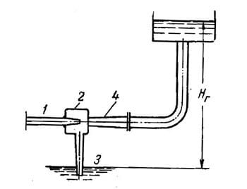
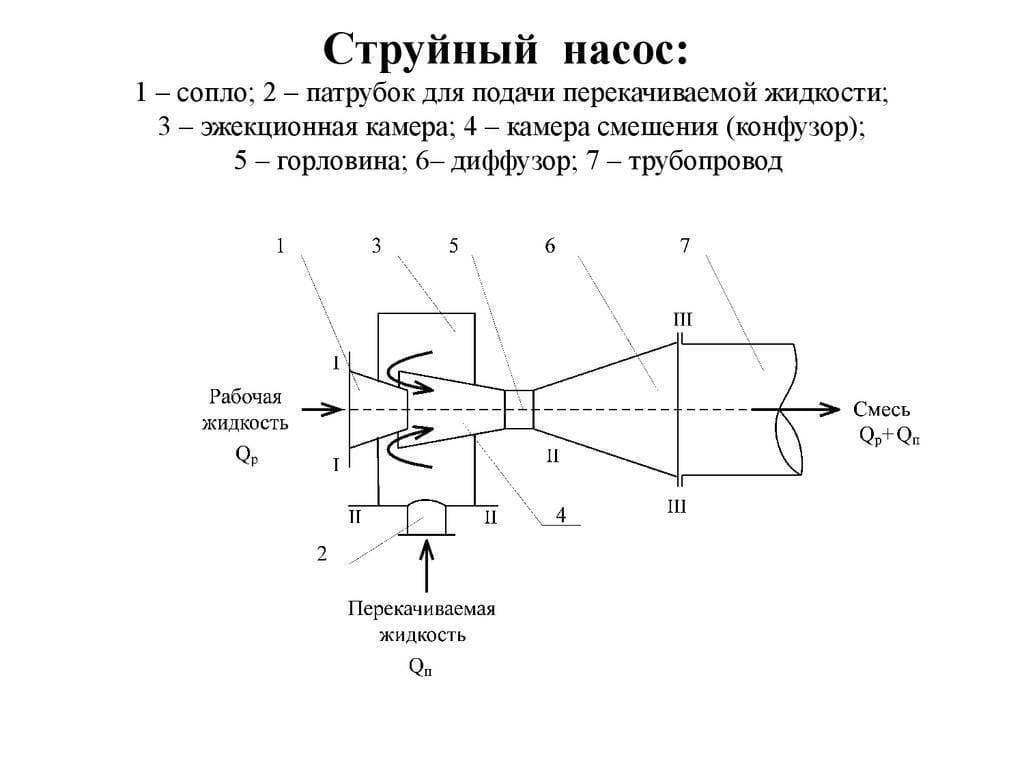
Figure 2 - Scheme of the jet pump
Picture 3 - The principle of operation of the jet pump
The fluid flow passes through the nozzle 1. The nozzle cross-section decreases along the length, so the flow rate gradually increases. At the same time, the kinetic energy of the flow increases, reaching its highest value at its exit from the nozzle into chamber 2.
An increase in kinetic energy causes a decrease in pressure in chamber 2. Under the influence of the difference between atmospheric pressure and pressure in chamber 2, the liquid rises from level 3 to chamber 2, where it is captured by a jet of working fluid flowing out of nozzle 1 at high speed.
The mixture of working and transported liquids enters the expanding branch pipe 4 and further through the pipeline into the tank to a height Hg [1].
Objectively, the jet pump is difficult to classify as a pressure device in the classical sense, since it does not provide excess pressure on the side of the flow discharge. A cylindrical nozzle as a jet pump is not used in practice, which is explained by the large energy losses in it. The structural diagram of a jet compressor used in industry is as follows [3]:
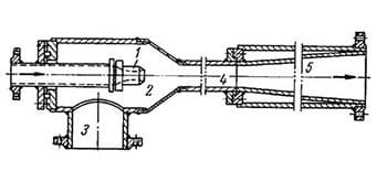
Figure 4 - Structural diagram of the jet compressor
The working fluid flows at high speed through the nozzle 1 into the receiving chamber 2. The jet of the working fluid in the receiving chamber comes into contact with the moving liquid entering through the pipe 3. Due to friction and impulse exchange on the surface of the jet in the receiving chamber, the liquid is captured and moved, coming through the pipe 3 into the mixing chamber 4 and further into the conical diffuser 5.
In the mixing chamber, there is an exchange of impulses between the working and transported fluids. In the diffuser, the process of converting kinetic energy into potential energy takes place. From the diffuser, the liquid enters the pressure pipeline.
Two types of jet compressors are common in industry: water jet and steam jet compressors. In water jet pumps, the working fluid is water, and in steam jet pumps, steam. The way water jet pumps and steam jet compressors operate is essentially the same; in their working process there is a difference due to the difference in the properties of the working fluids.
The main parameters of the jet pump are the flow rate of the working fluid Gр, the flow rate of the liquid transported by the pump Gн (pump flow), the pressure of the working liquid Рр, the pressure of the transported liquid Рн in front of the pump and the pressure of the mixed liquid behind the pump Рс [6].
The efficiency of jet pumps is low, but their simplicity of design and lack of moving parts have led to their widespread use.
Very often, the circuit diagrams for switching on jet pumps are assembled into a serial connection of several units. In this case, the pumps are designed with different nozzle diameters, which allows you to adjust the discharge flow characteristic in the operating range of the units connected in series [2].
3.2 Jet pump design
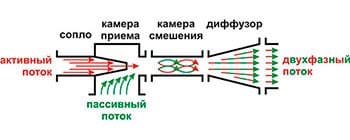
Figure 5 - Jet pump device
The design of the jet pump does not include moving parts. Depending on the purpose, it includes:
-nozzle of the unit;
-reception camera;
-mixing chamber;
-outlet diffuser;
-nozzles for supplying injected and working fluids (two-phase flow).
Different models of units of this type, depending on their area of application, are equipped with tapering nozzles of different characteristics - nozzles. The choice of nozzle in each particular case depends on the type of medium being pumped and its hydraulic features [9].
Advantages and disadvantages of jet pumps [7, 8]:
Like any equipment, jet pumps have their advantages and disadvantages. Let's try to summarize the main criteria for each of the categories.
The main advantages of jet pumps include:
- high reliability and the possibility of long-term operation without repair;
- there is no need to carry out regular maintenance;
- low sensitivity to chemically aggressive flows;
- simplicity of design and ease of installation;
- extensive area of use (in everyday life and industry).
Of course, most of the listed advantages of this type of pump over others come from the fact that they do not have moving components. Jet pumps are distinguished by relatively small overall dimensions and weight. They are undemanding to the cost of operation, which is a very significant factor in their application.
The main disadvantages of this type of aggregates are:
- very low efficiency of the pump - no more than 30%;
- the need to supply large volumes of liquid to the nozzle.
With the help of jet devices, gaseous substances are compressed, pressure is created below atmospheric - vacuum, liquid media are pumped, solid bulk substances are transported, various gases and liquids are mixed [5].
The field of application of water jet pumps in practice is extremely extensive and diverse. These pumps are also used in laboratories, where their scale is extremely small and where the conditions of their operation make it possible to use them in the simplest forms that are unsatisfactory from the hydraulic point of view. The same pumps are also used in industry, in construction (during hydromechanization of work) and in water supply for sucking air from pump chambers before they are started. Finally, water jet pumps are used in water heating and ventilation systems. The use of water jet pumps in heating systems and for hydromechanization has recently developed very strongly, and now these areas of work represent the main demand for water jet pumps, requiring improvement in their hydraulic forms and efficiency. It should be noted that a large number of theoretical and experimental work on water jet pumps is due precisely to the development of these areas of application of water jet pumps [3]. Therefore, leaving aside the issues of using water jet pumps in other areas (locomotive ejectors, pump ejectors, etc.), we will further consider the use of water jet pumps in water heating systems and in hydromechanization work. The latter area is of the greatest practical interest, since the scale of the pumps themselves and the overall scope of work, and, most importantly, the observed rapid development of hydromechanization will require a lot of further work from the scientific community and research institutes on the study and improvement of water jet pumps [4, 9].
4. Existing pump control methods
There are three ways to control the performance of the pump: throttling, regulation by bypass and changing the speed [1].
4.1 Throttling pump flow control
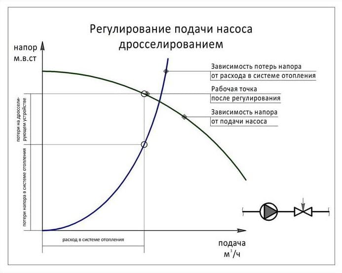
Figure 6 - Graph of pump flow control by throttling
Throttling is the simplest and most inefficient way to control the flow of a centrifugal pump. To throttle the flow, increase the hydraulic resistance in the pressure section of the pipeline common to the entire system, for example, immediately after the pump.
To throttle the flow, you can use automatic or manual control valves, or install a throttle washer.
During the throttling of the pump flow, the operating point moves up along the pressure-flow characteristic, while the head increases, and the flow and efficiency decrease [10].
4.2 Pump flow control by bypass
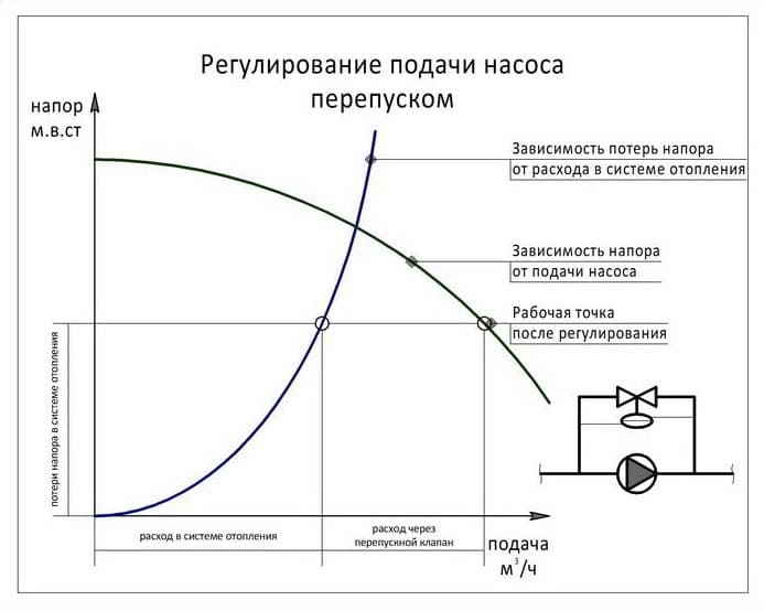
Figure 7 - Graph of regulation of pump flow by bypass
Bypass - to control the performance of the pump, a regulator is installed on the jumper between its inlet and outlet pipes to maintain a constant pressure drop across the pump (constant pump head). With a decrease in pump flow, the pressure created by it increases - the regulator reacts to the deviation of the differential from the set mark and opens by passing water from the pressure pipe to the suction pipe. Thus, the pump flow remains unchanged, and the water flow in the network can vary widely.
The advantage of this control method is that the pump always works with a constant flow and pressure in the zone of optimal efficiency, and the disadvantage is that with a decrease in the load in the network, the electricity consumption remains the same.
Pump flow control by bypass is used in heating systems with automatic control valves that change the flow depending on the heat demand of the building, as well as to include pumps that do not allow strong flow fluctuations in systems with a dynamic hydraulic regime [2, 9].
4.3 Adjusting the pump flow by changing the speed
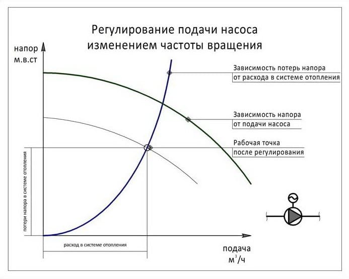
Figure 8 - Graph of pump flow control by changing the speed
Frequency control - installing an impeller speed controller is the most effective and most expensive method of controlling pump flow, since the cost of a frequency controller is commensurate with the cost of the pump.
The physics of this method is simple: by reducing the speed of the pump impeller by half, its flow is reduced by half, the head is reduced by four times, and electricity consumption is reduced by eight times [6].
Modern speed controllers can maintain a constant flow or pump head, or can change them depending on the needs of the system at different times of the day or days of the week.
Programmatically changing the speed of the impeller will not only ensure the operation of the pump with maximum efficiency, but will also reduce the noise that occurs during operation, perform a soft start, reduce starting currents and eliminate hydraulic shocks.
The regulation of the flow of a centrifugal pump by changing the engine speed is advisable in systems with frequent and strong fluctuations in water flow, as well as in the case of high energy costs. In such systems, the cost of a speed controller can pay off in a few months [10].
Advantages of the regulation method [3]:
- is more economical than throttling.
Disadvantages of the regulation method:
-allows only a limited change in flow due to a sharp deterioration in the cavitation qualities of the pump;
-in water supply systems, this method is not applicable at all, since it is impossible to supply water mixed with a large volume of air to the network.
-does not apply when pumping oil and oil products. When air is admitted into the suction pipe when pumping easily evaporating liquids, in addition to the cavitation phenomenon, an explosion may occur.
Findings
When writing the abstract, the ways of regulating water jet pumps were considered. The advantages and disadvantages of each of the methods were considered.
The work is aimed at finding the optimal way to regulate water jet pumps.
List of sources
- Kolomiets V.S., Zuykov A.L. Optimization of barrel parameters for the formation of an impulse jet. – Collection of science practices VISNIK of the Donbass State Machine-Building Academy. - 2005, No. 1.
- Lyamaev B.F. Hydro jet pumps
- Nedopekin F.V., Nechepaev V.G./ edited by prof., Dr. tech. Sciences A.N. Semko / Impulse high velocity liquid jets and their applications. - Donetsk: DonNTU, 2014. - 370s.
- Kolomiets V. S. Experimental studies of the regimes of jet formation of an impulse jet / V. S. Kolomiets, A. L. Zuykov. — Science practices of DonNTU. Vip. 14 (127) - Donetsk: DonNTU, 2007. - 306 p.
- Kolomiets V. S. Determination of the rational frequency of the jet of a hydraulic impulse installation for mining operations / O. A. Gemmerling. — Science practices of DonNTU. Vip. 18(172) - Donetsk: DVNZ DonNTU, 2010. - 282 p.
- Fridman B.E. Hydraulic elevators
- Научная библиотека [Электронный ресурс]. — Режим доступа: https://rep.bntu.by/bitstream/handle/data/29229/Sposoby_ochistki_regenerativnyh_vozduhopodogrevatelej_ot_otlozhenij.pdf?sequence=1
- Энергетика справочник [Электронный ресурс]. — Режим доступа: http://mir-diplom.ru/file.php?workF=wfabbf
- Rzhanitsyn N.A. Water jet pumps
- Kamenev P.N. Hydraulic elevators in construction