
Abstract
Content
- Introduction
- 1. Relevance of the topic
- 2. Purpose and objectives of the work
- 3. Requirements for test benches according to Gost 8.156-86
- 3.1 Description of the requirements for verification by the flow precision flow meter
- 3.2 Basic requirements for installations for checking meters by mass measurement
- 4. Investigated water meters
- 5. Prototype system
- 5.1 Purpose and scope
- 5.2 Technical specifications
- 5.3 Composition, device and operation
- 6. Flow meter selection
- Conclusions
- List of sources
Introduction
Almost all residential, commercial, warehouse and other types of premises have meters that record the water flow in them. However, the fact that the owner of the premises, or persons authorized by him, periodically take current readings from the meters, is by no means all ...
These metering devices need periodic inspection, which is carried out by appropriate specialists with proper accreditation and special equipment. What are the options today for conducting meter verification, which, according to the standard, should take place once every 4 years for hot water meters and once for 6 years for cold water meters?
Option one, to check directly at the location of the metering device, with a portable calibration unit, in the current realities is not the most accurate option;
The second way is to check with a representative of the housing and communal services, where it will be checked at stationary stands and if your meter is functioning problematically, you will be notified in writing in a timely manner, in which case it must be repaired or immediately replaced and put a new one on the register in the presence of a representative of the housing and communal services;
The third method is not quite the optimal way, in which you can not perform meter verification and just pay several times more expensive for the water consumed, since you will pay not for how much you spent, but for how much you are prescribed.
Therefore, we can conclude that it would be most rational to pay for a serviceable and trusted meter, as well as contacting the housing and communal services service if verification is necessary, in this case, payment will occur according to the amount of water consumed and no one will overpay or remain at a loss due to a faulty meter.
Test stands are precision measuring instruments and guarantee a maximum error of 5%, their development and maintenance is a complex and very responsible process, therefore specialized companies are engaged in this.
1. Relevance of the topic
Every year the number of household flow meters, both hot and cold water, is steadily growing. Like all measuring devices, flowmeters require verification, since over time their readings may and will differ from the correct ones. Also, every year electronics does not stand still, and human resources are limited, so there is a need to reduce the cost and automate the process of checking flow meters without losing the accuracy of verification.
2. Purpose and objectives of the work
The purpose of the work: to study the operation of stands for checking household flow meters and, based on the study, to substantiate and develop the structure of the electronic system of the stand for checking household water meters.
The main objectives of the study:
- Perform an overview of methods and tools for monitoring and analyzing the verification of household flow meters.
- Formulate technical requirements for the development of the structure of the ES stand.
- To develop a block diagram and an algorithm for the functioning of the stand.
- Develop a schematic diagram of the stand.
- Select and justify the element base satisfying the verification Gost-8.156-86.
- Perform a calculation of the economic efficiency of the project.
- To work out the issues of production safety and labor protection.
The object of the study: a calibration stand of household water flow meters.
Subject of research: reduction of hardware and financial costs when implementing a stand based on an ATmega controller.
3. Requirements for test stands according to Gost 8.156-86
3.1 Description of the requirements for verification by the flow precision flow meter method
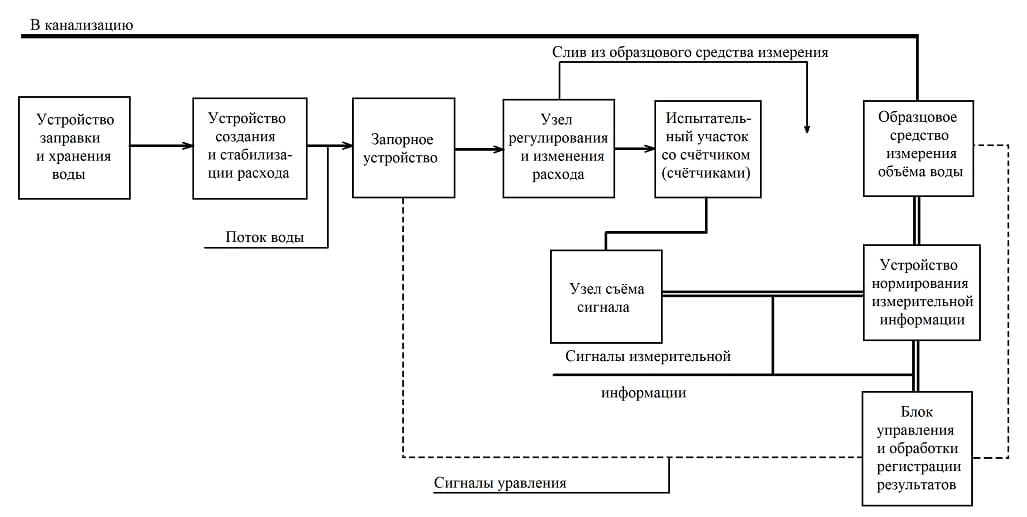
Figure 1 – Block diagram of an automated calibration unit
The verification installation must consist of the elements indicated in the diagram:
- devices for filling and storing water (pump, filters and water tank);
- devices for creating and stabilizing flow (pump, pulsation dampener and adjusting device);
- shut-off device (valve, valve with manual, pneumatic or electric drive). When using electro-pneumatic locking devices, their opening and closing are carried out automatically after filling the sample measure to the level of a given volume;
- the test section intended for the installation of meters in the line of the calibration installation (compensators for the length of the pipeline, straight sections of pipes, inlet and outlet pipes providing hermetic connection by manual or any mechanized method). The length of the straight section in front of the first counter is at least 5 diameters of the conditional passage and one after each;
- an exemplary means of measuring the volume of water. It may include metal technical measuring instruments of the 1st class according to GOST 13844 -68, metal model measuring instruments of the 2nd category according to GOST 8.400 -80 scales or model liquid counters;
- an optoelectronic signal pickup unit that generates pulses corresponding to the rotation indicator. They are fed into the device for normalizing signals of measuring information;
- measuring information normalization device, which starts counting measuring information signals simultaneously with the start of measurement with an exemplary measure passed through a verifiable counter, and stops counting at the end of measurement;
- control unit designed to ensure the execution of the necessary sequence of operations and the formation of measuring information signals in a form convenient for taking readings and comparing with readings an exemplary measure;
- a flow control and measurement unit consisting of a device that provides smooth flow control (if necessary in two or more mutually overlapping ranges) and flow measurement tools in the entire range of calibration costs. In particular, it is recommended to use rotameters, flowmeters, electromagnetic flowmeters, ball flowmeters according to GOST 28723-90.
3.2 The main requirements for installations for the verification of meters by the method of mass measurement
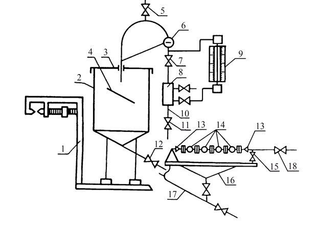
Figure 2 – Schematic diagram of the installation for checking meters by measuring mass
- mass measuring device;
- container;
- container lid;
- jet extinguisher;
- air vent valve;
- peephole;
- nozzle tap;
- sight glass;
- flow meter;
- supply pipeline;
- control valve;
- drain valve;
- device for connecting meters;
- counters;
- drain tap;
- stand;
- drain pipe;
- shut-off valve (valve).
As a device for measuring the mass, scales are taken, the relative error of which should be within ± 0.5% for checking the counters at the 1st and 2nd calibration flow and + 1% for checking the counters at the 3rd calibration flow.
The maximum load of the scales should be 20% more than the mass of the container filled with water, including the mass of all connecting devices.
The installation, regardless of its location, must be protected from the effects of atmospheric precipitation and air currents.
The capacity of the container installed on the scales must be at least 10% more than the volume of water that passed through the meter during its verification, depending on the diameter of the conditional passage and the installed flow rate.
All flexible pipe connections must be made in such a way that their effect on the sensitivity of the scales is the least.
The pipelines are attached to the container on one side and attached to a bracket that is not connected to the scales.
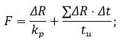
Note. When checking the counters on a calibration installation in which scales are used as an exemplary means, it is allowed up to a temperature of 15 ° C to consider the resulting mass value equal to the measured volume, and at temperatures over 15 °The resulting mass value is multiplied by a correction factor that takes into account deviations in the density of water for every 5 ° C and the loss of mass of liquid in the air, according to the formula:
where G is the mass value, t,
C is a correction factor that takes into account the change in density from temperature, m/t (see Table 1).
| T,°C | 20 | 25 | 30 | 35 | 40 |
|---|---|---|---|---|---|
| C | 1.003 | 1.004 | 1.005 | 1.006 | 1.007 |
4. Investigated water meters
Special flow meters are used to account for the consumption of hot or cold water. Whose representative will be the IED counter 15.
It belongs to the category of high-class measurement accuracy devices. For this reason, the device is approved for use in private homes or apartments where a centralized supply of hot or cold liquid is carried out.
Thanks to the use of this type of water meter, economical people manage to minimize the cost of utility bills.
The water flow meter SVU 15 is a single-jet dry-water metering device for water consumption. Such a device consists of a metal case in which the measuring chamber and the counting mechanism are reliably separated from each other. An impeller drum is installed in the measuring chamber, which begins to rotate under the pressure of water.
The shaft turns, and the movement is transmitted through the gearbox to the counting mechanism. If the device is equipped with a pulse output, then in addition to mechanical calculation of the flow rate, remote transmission of the signal from the meter to the receiving device is possible.
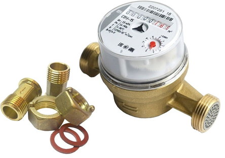
Figure 3 – Water meter, IED model 15
5. Prototype system
Let's consider the existing prototype on the example of an automated installation for checking UPV-15/20 water meters.
Figure 4 – Operation of the stand
(animation: 32 frames, repeating cyclically, 77.5 kilobytes)
5.1 Purpose and scope of application
Automated installation for checking water meters AUPV-15/20 designed for simultaneous verification of up to ten winged water meters with a diameter of a conditional passage of 15 mm and up to eight water meters with a diameter of a conditional passage of 20 mm by measuring the mass of water spilled through the water meters and automatic generation of reports and passports on the verification of water meters.
The stand allows for the verification of water meters by setting the flow and volume in the ranges required by GOST 8.156-88 For setting and reading the pulses of water meters, the stand is equipped with optical data collection nodes. Display of data read from water meters: current flow, estimated error, adjustment criteria and the screen of the digital oscilloscope of the optical data acquisition node; be displayed on the monitor screen.
The stand does not require the supply of water supply and sanitation networks.
The stand allows for verification, both in automatic and manual modes.
According to the operating conditions, the stand complies with UHL 3.1 according to GOST 15150, is designed for operation at ambient temperatures from +10 ° C to +40 ° C and relative humidity from 20% to 80%.
5.2 Technical specifications
- The stand simultaneously checks up to 10 water meters.
- The diameter of the conditional passage of the verified water meters is 15 mm, 20 mm.
- The range of set flow rates is from 28 l/h to 2500 l/h.
- The margin of error when maintaining the 1st verified flow rate is not more than ± 2%.
- The margin of error when maintaining the 2nd and 3rd verified expenses is not more than ± 2%.
- The volume of the measuring capacity is 72 liters.
- The volume of the water storage tank is 130L.
- The response time of the water flow distributor is not more than 0.1 seconds.
- The limit of permissible error of the scales is not more than 0.2%.
- The stand is powered by a three-phase AC network with a voltage of 380V ± 10% and a frequency of (50 ± 1) Hz.
- The power consumption of the stand does not exceed 1500 watts.
- The weight of the stand is not more than 300 kg.
- Overall dimensions are not more than 3100x820x1560 mm.
5.3 Composition, structure and operation
The stand consists of the following nodes:
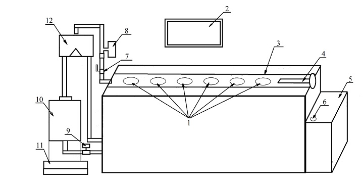
Figure 5 – General layout of the stand
- water meters;
- screen;
- test area;
- clamping mechanism;
- power and control cabinet;
- toggle switch on/off the stand;
- ball valve
- electromagnetic flow meter with frequency output;
- electric ball valve;
- weighing capacity;
- scales;
- water flow distributor;
The stand also includes: optical data collection nodes, a personal computer and a printer. The optical data acquisition node consists of the following elements:
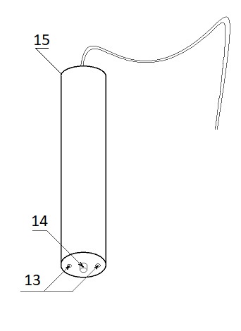
Figure 6 – Optical data acquisition node
- - IR LED;
- - photodiode;
- - node for optical reception of water meter pulses ("Pencil");
The automated installation for checking water meters (hereinafter referred to as the stand) can operate in 5 modes:
1) verification of water meters by measuring the mass spilled through water meters;
2) checking in manual mode by comparing the readings of the counting mechanism of the water meter and the volume of water calculated by weight;
3) calibration of the reference flow meter by measuring the mass of water spilled through it;
4) verification of the reference flow meter by measuring the mass of water spilled through it;
5) verification of optical data acquisition nodes by comparison with the readings of the counting mechanism.
The stand sets and maintains the water flow during the calibration automatically. The value of the current flow rate is determined by the system via the digital interface of the electromagnetic flow meter. The StandWDK software (hereinafter referred to as the software) compares the current flow rate with the specified (verification) one and determines the error of setting the flow rate. The speed of rotation of the pump motor shaft is determined by mistake. The frequency of the motor shaft is directly proportional to the power frequency of the three-phase asynchronous motor.
The automated installation for checking water meters has a closed cycle of water turnover. The pumping unit supplies water through a system of flexible hoses to the test area with water meters. Up to 10 water meters with a diameter of 15 mm and up to 8 water meters with a diameter of 20 mm can be verified at the test site. When checking a smaller number of water meters, intermediate inserts with DN = 15 mm are used. When checking counters with a DN of 15 mm, adapters of DN 20/15 are placed at the entrance and exit of the test area.
An infrared sensor (ID) of the optical data acquisition node is installed on the asterisk of each water meter, which generates pulses with a frequency proportional to the rotation speed of the asterisk. UOSI analyzes the repetition rate and pulse skips. Pulse skipping may occur due to an obstacle in the path of the beam of the UOSI sensor, a damaged water meter sprocket, damaged water meter mechanics or an inappropriate installation of the ID. UOSI has a built-in signal gain controller from an infrared sensor to compensate for differences in the reflective surfaces of different water meters.
At the outlet of the test area there is a pressure gauge, a valve and a check valve. The pressure gauge is designed to display the pressure when checking the hydraulic tightness of the water meters at the test site. Behind the valve there is a check valve and an electromagnetic flow meter "Take-off" with a frequency output. The check valve is necessary to ensure the smooth operation of the flow meter. The "Take-off" flow meter is used as a device for determining and setting the flow rate of verification. A frequency output and a digital interface are used to connect the flow meter to the stand. The frequency signal of the flow meter determines the amount of water spilled during one spill with an accuracy of 1/1600 liters. The current flow rate required for the flow maintenance controller is read via the digital interface.
Behind the stand on the right side there is a rack with scales. The scales are equipped with an indication and a keyboard. Weight information is sent to a personal computer via RS-232. On the scales there is a water tank with a capacity of 72 liters. The tank has a drain and overflow at 73 liters. There is an electric ball valve on the drain, controlled by software. An RV is installed on a rack with scales above the tank. One direction of flow is into a container for weighing water, the second - into a container for storing water. The control commands are sent from the PC to the control unit of the automation of the stand, which controls the RV drive. The drive of the water flow distributor has a linear dependence of displacement on time and redirects the flow in a time less than 100 ms. A mechanical spring lock is used to fix the RV tray in the extreme positions.
A digital temperature sensor is built into the water weighing tank to convert the mass of water into volume.
At the entrance of the test area after the ball valve 1, a system for checking the tightness of water meters (SPGV) is connected. LNG creates a pressure of up to 30 atm.
Flow control is carried out by the method of frequency control of the pump unit motor. The frequency converter generates a 3-phase power supply to the pump with a frequency set by the controller. The rotation frequency of the pump shaft is directly proportional to the frequency of the supply voltage. The frequency is calculated by the flow controller according to the proportional-integral control law:
where ΔR=Rest-Rcur;
Δt - pump frequency calculation period (0.25 sec);
kp - proportional component of the control law;
tu - integral component of the control law;
Rуст - setting the flow rate. Set to the flow controller by the operator/program;
Rтек - the current value of the flow. It is determined by the interface output of the electromagnetic flow meter.
6. Choosing a flow meter
The flow meter that satisfies us will be the "ER-U Take-off".
The electromagnetic flow meter "VZLET ER" is designed to measure the average volumetric flow and volume of hot and cold water, household wastewater, as well as other non-aggressive electrically conductive liquids in wide temperature ranges and conductivities.
The main scope of application of flowmeters "TAKE-OFF ER" as part of heat meters, measuring systems, automated process control systems in energy, utilities, etc.
Flowmeters can be installed in both metal and plastic (metal-plastic) pipelines. On request, the flowmeters can be configured to measure the parameters of the reverse flow with the output of a flow direction signal.
The limits of the permissible relative error of the flow meter when measuring, indicating, recording, storing and transmitting the measurement results of the average volumetric flow rate, the volume of various liquids for flow meters in any flow direction in the flow range from 0.0067*Qnaib to Qnaib (the overlap coefficient of the range is 1:150) are determined by the formula:
where 𝛿 – limits of permissible relative error;
v – the flow rate in the pipeline, m/s.
The relationship between the flow rate v and the flow rate in the pipeline Q is determined by the dependence:
where Q – average volume flow, m3/h;
Dy – the diameter of the conditional passage, mm.
For flowmeters, the limits of permissible relative error in any flow direction - 𝛿 = ± 2,0%.
Conclusions
As part of the work, schematic diagrams of stands for checking water meters were considered.
The structure of the analog stand has been studied in detail on the example of an automated installation for checking UPV-15/20 water meters.
A flow meter is selected that is not inferior in measurement errors to the UPV-15/20 stand and complies with GOST 8.156-86.
The master's thesis is devoted to the actual scientific problem of automation and optimization of data acquisition during the verification of household meters.
Within the framework of the conducted research, the following was performed:
- The review of methods and means of control and analysis of verification of household flow meters is carried out.
- The technical requirements for the development of the structure of the ES stand are formulated.
- A block diagram and an algorithm for the functioning of the stand have been developed.
- A schematic diagram of the stand has been developed.
Further work is aimed at solving the following tasks:
- Calculate possible errors when reading signals and take possible measures to eliminate them.
- Development of a structural and schematic electronic circuit for the stand.
- Justification and selection of the element base satisfying the verification GOST-8.156-86.
- Performing the calculation of the economic efficiency of the project.
- To work out the issues of production safety and labor protection.
When writing this abstract, the master's work has not yet been completed. Final completion: June 2023. Full text of the work and materials on the topic can be obtained from the author or his supervisor after the specified date.
List of sources
- VIAD 2.833.002 TU. SHV cold water meters (SHV-15, SHV-15D, SHV-20, SHV-20D) and SGV hot water meters (SGV-15, SHV-15D, SGV-20, SGV-20D). Technical conditions.
- GOST 2.729-68. Unified system of design documentation. Conventional graphic designations in diagrams. Electrical measuring devices.
- GOST 2.770-68. Unified system of design documentation. Conventional graphic designations in diagrams. Elements of kinematics.
- GOST 50601-93. Drinking water meters are winged. General technical conditions.
- GOST 8.156-83. Cold water meters. Methods and means of verification.
- MP 4213-200-18151455-2001. Cold and hot water meters VSH, VSHd, VSG, VSGd, VST.
- The flow meter is an electromagnetic "TAKE-OFF ER-U".
- Manual for the operation of an automated installation for checking water meters UPV-15/20.
- SanPiN 2.1.4.1074-01. Drinking water. Hygienic requirements for the water quality of centralized drinking water supply systems.