
Abstract
Content
- Introduction
- 1. Technological process as an object of automation. The purpose of the design and requirements for the automation device
- 2. Critical review of existing solutions and selection of basic automation equipment
- 3. Justification of the direction of automation of the technological installation
- 4. Algorithmization of monitoring and control of the technological process of the mine boiler plant
- 5. Technical implementation of the thermal load management system of the mine boiler plant
- 5.1. Block diagram of an automated process monitoring and control system for mine heat supply
- 5.2. Technical description of mine boiler plant automation equipment
- Conclusions
- List of sources
Introduction
Automation of technological processes is one of the decisive factors in increasing productivity and improving working conditions. All existing and under construction industrial facilities are equipped with automation tools to one degree or another. Thereby automating production.
The effectiveness of automation is manifested, first of all, in the growth of labor productivity. Automation allows you to completely free a person from the execution of cyclic processes or processes running according to a strictly specified algorithm.
Thermal power plants are characterized by the continuity of the processes occurring in them. At the same time, the generation of thermal and electrical energy at any given time must correspond to consumption (load). Almost all operations at thermal power plants are mechanized, and transients in them develop relatively quickly. This explains the high development of automation in thermal energy.
1. Technological process as an object of automation. The purpose of the design and requirements for the automation device<
The boiler house belongs to dangerous production facilities and the main requirement for them is to ensure the proper level of safety. The operation of boilers must ensure reliable and efficient steam generation of the required parameters.
Based on these requirements, automated process control systems have become widely used, which, without the constant presence of a person, maintain the optimality of the technological process and increase efficiency.
The master's thesis is devoted to the actual scientific task of developing a system for automatic control of the thermal load of a mine boiler plant. This automation direction will save fuel up to 8%, increase boiler efficiency by 7–8% [1], ensure the operation of the furnace from an overabundance of air, reduce electricity costs for air supply and reverse thrust [2], reducing the amount of repair work and improving the service culture.
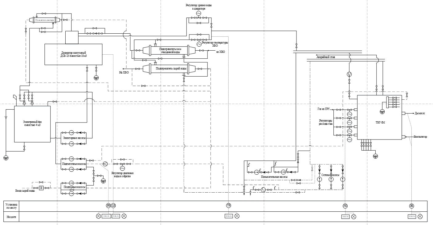
Image 1 – Block diagram of a mine boiler plant
The requirements for the automated system for monitoring and controlling the heat supply of the mine [3] are as follows:
1 Before the boiler room is lit, the boiler is purged for 15 minutes.
2 Local and automated types of management should be provided.
3 Control of the following parameters: discharge; low air pressure; low water flow; low gas pressure; low/high water pressure ;high temperature; torch.
4 Automatic protection
5 Emergency stop of the boiler occurs when: low discharge in the boiler furnace; low air pressure; low water flow; low gas pressure; low/ high water pressure; high water temperature at the outlet of the boiler; flame is not gorenje.
6 Availability of the following types of alarm: warning; emergency; technological.
7 Visualization of all parameters on the control unit of the automation system.
8 Transfer of information about the operation of the boiler and the control unit to the personal computer of the automated workplace of the boiler room dispatcher.
9 The unit must be in a moisture-proof housing, the connection circuits must be intrinsically safe.
2. Critical review of existing solutions and selection of basic automation equipment
The P25 controller [5], at the time of its birth, turned out to be a rather successful and, accordingly, in-demand development. In total, 3 modifications of the device were produced, which differed in the type and number of outputs:
– P25.1 – designed to connect yes three diftransformer sensors;
– P25.2 – connection of one or two thermal resistances;
– P25.3 – connection of the thermocouple HA, HC or PP.
All modifications allowed the use of unified signals (0...5 mA, 0...20 mA or 0...10 V).
In addition, each modification of the P25 controller was produced in two versions – with an indicator of the position of the actuator (devices with the digit "2" at the end) or without it ("1").
The device turned out to be really successful, convenient to use and quite easy to repair. But over the years it has become obsolete, radio elements have failed and at the moment they are almost not repaired.
And enterprises are trying to replace them with newer and more modern regulators.
To switch to a more modern controller, you need to make a list of requirements that this device must meet so that the transition from P25 is as simple as possible:
– the device must correspond to the P25 controller in terms of inputs, outputs and power supply (it is desirable that there are more inputs and outputs, and that they are more universal in terms of signal types);
– the device must ensure the nature and quality of regulation no worse than P25 (preferably, except for the PI-pulse and two/three-position structures implemented in the P25 controller, have the ability to choose the type of regulation (analog, pulse or PWM) and the ability to automatically correct the task (along a curve or by an external signal) based on the needs of the technological process);
– work in temperature ranges -5...+40°C;
– operate from a voltage of 20...270 V
– work with parameters: discharge, pressure, flow, temperature.
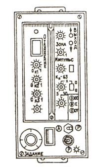
"Images 2 – Front panel of the p-25 controlle
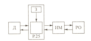
"Images 3 – Schematic diagram of automatic control
3. Justification of the direction of automation of the technological installation
Since the main problem at the boiler plant is associated with incomplete combustion of fuel, due to an outdated control system. Therefore, when choosing and creating an algorithm of work, it is necessary to make a conceptual model of the object under study.
Boiler Parameters:
– Heat boiler capacity of 8.3 MW (8 Gcal/h);
– Blast fan type C-13-50 No. 5 with a capacity of 13,000 m3/h, the maximum operating pressure at which the alarm is triggered is 10 mm.water;
– Discharge, maximum operating pressure 0.8 mm.water;
– Water flow through the boiler 104 m3/h;
– Exhaust gas temperature, 150C
– Water temperature : at the inlet 70C; at the outlet 150C.
– Gas consumption 1100 m3/h;
– boiler efficiency of 90%;
– Water pressure: max 14 kg/cm2; min 8 kg/cm2.
Let's make a design diagram of the identified object (Figure 4), where KU is a boiler installation, BR is an adjustment unit that adjusts the opening /closing of the valve to supply a certain amount of gas and air to the boiler furnace, as well as adjusting the discharge in the boiler furnace.
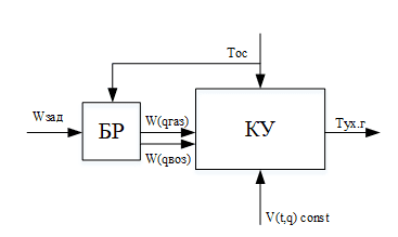
Images 4 – Calculation scheme of the identified object
The input signal V(t,q) of the const model is a constant value of Tt.n vx and Qt.n g.v, the output Y(t) is the temperature of the exhaust gases. The disturbing factor is the ambient temperature. Regulating W(qgaz) of gas flow and W(qvoz) of air.
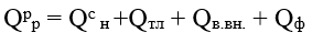
The calculations set out below are carried out in order to determine the efficiency of the boiler and fuel consumption.
Calorific value of a unit volume of dry gas, Qc h
Heating of fuel and air outside the boiler unit is not provided. There is also no nozzle blowing.
Qтл – fuel heating;
Qв.вн. air heating outside the boiler unit;
Qф –nozzle heating.
Then the available heat:
Heat loss and efficiency of the boiler.
Cold air temperature, tх.в.
Enthalpy of theoretically necessary air, Io х.в.
Exhaust gas temperature, vух
Coefficient of excess air in exhaust gases auch aух
Enthalpy of combustion products at this temperature, Iух
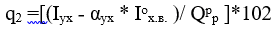
Heat loss with outgoing gases:
Heat loss from chemical incompleteness of combustion,q3
Heat loss from mechanical underburning,q4
Heat loss by boiler and economizer surfaces, q5
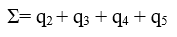
Total heat loss by boiler unit:
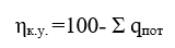
Efficiency of the boiler unit:
Fuel consumption at rated thermal load.
Thermal load during boiler operation in hot water mode, Qк
Calculation of boiler fuel at rated load:
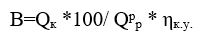
Estimated fuel consumption, Вр =В
All calculations are given in the master's thesis.
4. Algorithmization of monitoring and control of the technological process of the mine boiler plant
The boiler house belongs to dangerous production facilities and the main requirement for them is to ensure an adequate level of safety. The operation of boilers must ensure reliable and efficient steam generation of the required parameters.
Based on these requirements, automated process control systems have become widely used, which, without the constant presence of a person, maintain the optimality of the technological process and increase efficiency.
The scheme of automation of regulation and control of a gas boiler unit should provide for the following systems:
– automatic control and control system of the gas-air ratio;
– automatic regulation and control of the discharge in the boiler furnace;
– automatic control and monitoring of water pressure in the return pipeline;
– automatic control and level control system in the deaerator tank;
– automatic control and control of the water temperature of the HVAC.
Since the period of use of the P25 controller significantly exceeds the period of its maximum operation, it is not advisable for further use. The reasons for this:
– an increase in the error due to the obsolescence of radio elements;<
– maintainability;
– frequent failures of setters, switches B/M and A/R.
In this regard, it was decided to develop a replacement for this regulator, and switch to PLC-150 [6], which will allow you to change and adjust the algorithm of the boiler room by entering a new program, or simple corrections of the programmed program.
If the parameters were violated at the time of the system polling, the error information is displayed and the alarm is activated[8].
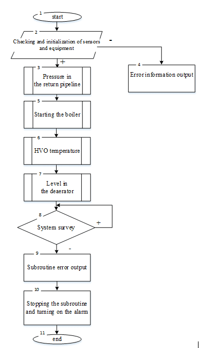
Images 5 – Heat supply algorithm of boiler plant
The gas-air ratio must be set using a computer or a manual setpoint, the temperature in the furnace areas and the air flow are controlled by a controller or a manual control unit. Low pressure signaling in the mains is organized in accordance with the existing parameter signaling scheme. When the pressure in the gas or air lines is low, the corresponding indicator should light up and a sound signal should sound. The removal of the signal by pressing the button must be provided in the system.
If the control occurs in manual mode, the algorithm stops its operation. In automatic mode, the toggle switch on the control panel selects the task setting mode (from a manual setter or computer). In the mode of setting the task from the manual setpoint, a mismatch is applied to the input of the controller, equal to the difference between the temperature setting from the manual setpoint and the temperature in the zone. In the task setting mode, a mismatch is applied from the computer to the input of the controller, equal to the difference between the temperature setting, the specified computer and the temperature.
When selecting the automatic operation mode. The controller starts initialization of all system devices, their operability and communication integrity. Waits for the command to start the boiler ventilation routine before starting.
After the ventilation is over, a command is given to start the subroutine of alternate ignition of the burners, and their output to the minimum gas consumption.
Next, the ambient temperature sensor is interrogated, and after that the program compares the readings and sets the gas-air ratio with the operating map of this boiler.
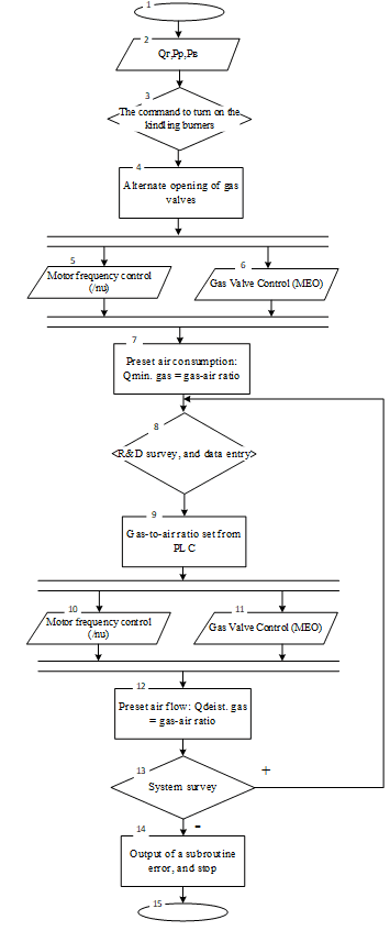
Images 6 – Boiler start routine (gas-air ratio)
The "Boiler start-up" routine begins with a survey of gas flow sensors, air pressure and discharge in the furnace. Next, a 15-minute purge of the boiler is turned on and the kindling burners are turned on. After 15 minutes have passed, the program starts alternately opening the gas valves and adding air so that the flame does not go out. Then the controller polls the ambient temperature sensor, and compares it with the boiler load schedule.
If any parameter was violated at the time of the system survey, the system outputs an error and stops the gas supply to the boiler furnace.
5. Technical implementation of the thermal load management system of the mine boiler plant
5.1. Block diagram of an automated process monitoring and control system for mine heat supply
In accordance with the algorithm of work, a two-level structure of an automated process monitoring and control system is created [7].
The upper level is the level of management of the production process and resources of the enterprise. The upper level is the control room of the mine, which receives information from the main technological nodes of the mine boiler house.
The lower level is the level of control and monitoring of the parameters of the technological process, its visualization. This level consists of an operator's workstation, a mutual inductance conversion unit and sensors.
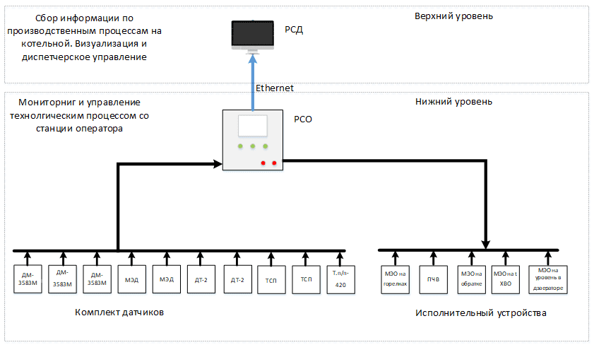
Images 7 – Block diagram of the automated monitoring and control system of the mine boiler plant
Data on the technological process are received from a set of sensors (DM-3583M, MED, DT-2) to the operator's workstation of the RSO, through the mutual inductance conversion unit, the remaining sensors with a unified signal directly. The output signals are sent to the actuators (MEO, frequency converter). Data from the RSO is transmitted to the workstation of the RSD dispatcher or PC over an Ethernet network. Archiving and visualization of process data takes place on the RSD. The main control takes place on the RSO.
5.2.Technical description of mine boiler plant automation equipment
The automated control system "Universal" is designed for automatic ignition, control, regulation and protection of the TVG-8M boiler [9]. In combination with sensors and actuators, Universal is a powerful system that meets all modern requirements for boiler control systems of this type.
"Universal" provides the following functionality:
– automatic ignition of the boiler (when the START button is pressed);
– checking the tightness of the gas pipeline when starting the boiler;
– technological stop of the boiler followed by after-stop ventilation of the furnace (when the STOP button is pressed);
– emergency stop of the boiler with the termination of the gas supply with an audible alarm and indication of the cause of the accident in the case of:
– high pressure gas in a suitable gas pipeline;
– low gas pressure in a suitable gas pipeline;
– low air pressure in front of the burners;
– low vacuum in the boiler furnace;
– low water pressure at the boiler outlet;
– high water pressure at the boiler outlet;
– high water temperature at the outlet of the boiler;
– extinguishment of the flame;
– emergency stop of the fan;
– emergency stop of the smoke pump;
– emergency stop of the feed pump;
– automatic regulation of the vacuum in the boiler furnace;
– automatic gas pressure control in front of the burners;
– automatic air pressure control in front of the burners.
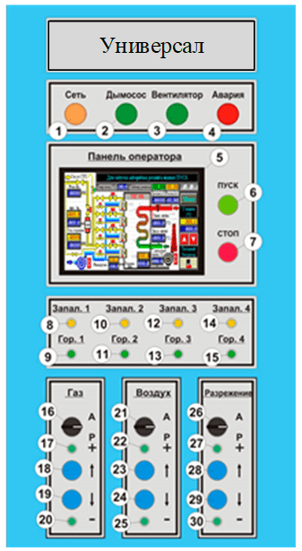
Images 8 – Appearance of the front panel of the control cabinet
Technical Features:
– LCD provides clear resolution under all lighting conditions;
– the system prevents data loss in case of power failure;
– high operating temperature;
– data transmission is carried out using an Ethernet cable. USB;
The means of collecting information is a set of sensors, which consists of 10 analog sensors. Differential sensors (DM3583M, MED, DT2) have an output signal of mutual inductance 0-10 (-10...+10) MH, a previously developed unit for converting mutual inductance to the 4-20mA standard was adopted, temperature sensors are connected to analog inputs.
The actuators are the MEO, frequency converters of the fan and the smoke pump.
Master SCADA has been adopted for visualization, monitoring and process control [10].
The advantages of this system are as follows:
– a simple and intuitive Russian-language interface;
– access from any workplace to any information available in the system and interaction with other programs using modern technologies;
– detailed reference material and tooltips;
– control of the validity of the entered information;
– compliance of the project with the logic of perception of the system and the object by the developer;
– the possibility of full debugging of the project without connection with the object and the possibility of full debugging of a distributed system on one computer;
– no need to configure the network or allocate a separate server to run a distributed system;
– the ability to reuse any previously created part of the project;
– libraries of technological objects from various fields;
– automatic and custom processing of quality signs of values and simulation mode with individual selection of signal simulation functions.
As a result of the performed studies of the computer model of the mine boiler plant, the work model was modeled.
Images 9 – Mnemonic diagram of boiler plant operation
(animation: 4 frames, 314 kilobytes)
During operation, the control panel analyzes the state of the boiler by means of information coming from analog and discrete sensors, and generates control actions on the actuators.
After the supply voltage is applied, the shield is in its original state. The "Network" indicator is lit on the front panel. The operator panel displays the "Main Screen". The shield measures and displays all boiler parameters on the main screen. Before starting the boiler, all the switches of the regulators must be in the automatic control position. After pressing the "START" button, the boiler ignition algorithm begins.
From the moment of pressing the "START" button until the boiler enters the performance control mode, the boiler control panel performs a number of technological operations, which are divided into time intervals. Each time interval assumes the activation (deactivation) of certain actuators, the presence (absence) of control over certain protection channels and sets the operating modes of regulators.
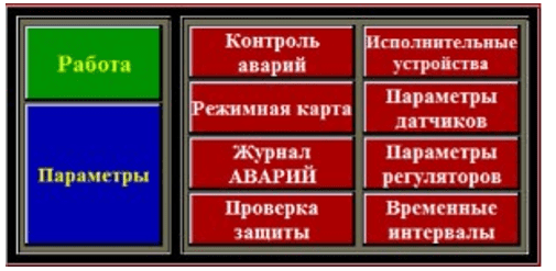
Images 10 – Main screen
All control is carried out by displaying the corresponding windows on the screen: "Main screen", "MENU" screen for configuring the system, "Ventilation parameters", "Ignition parameters", etc.
Conclusions
As a result of the analysis of the operating modes of the boiler house as objects of monitoring and control, the requirements for the monitoring and control system of the heat supply of the mine are formulated, the distinctive feature of which is the presence, along with the standard requirements of regulatory documents, the requirements for coordinated control of operating modes and regulation of their parameters depending on the ambient temperature.
A two-level computer-integrated control system using an industrial network has been developed. At the upper control level there is a subsystem for dispatching monitoring and coordination of the work of the heat supply of the mine, and at the lower level there is a subsystem for controlling the boiler room. Technical means of automation have been justified and adopted for each subsystem.
When writing this abstract, the master's work has not yet been completed. Final completion: June 2023. The full text of the work and materials on the topic can be obtained from the author or his supervisor after the specified date.
List of sources
- Топливо, топки и котельные установки. Щеголев М.М. 1953. 4-е издание переработанное, 546 с.
- Справочник по теплоснабжению и вентиляции. Книга 1. Отопление и теп-лоснабжение. Щекин Р.В. и др. 1976. 352 с.
- Справочник по автоматизации котельных. Под общей редакций канд. тех. наук Л.М. Файерштейна. и др. 1978. 173 с.
- Тарасюк В.М. Эксплуатация котлов: Практическое пособие для опера-тора котельной, г. Москва, 2008 г
- Руководство по эксплуатации Р25: https://promav.nt-rt.ru/images/manuals/r-25.pdf
- Руководство по эксплуатации ПЛК 150: https://owen.ru/uploads/re_plc150_1772.pdf
- Егоров С.В., Мирахмедов Д.А. Моделирование и оптимизация в АСУТП. М. 1988
- Баховцев, И.А. Микропроцессорные системы управления устройствами силовой электроники. Структуры и алгоритмы [Электронный ресурс]: учеб-ное пособие/ Баховцев И.А.— Электрон. текстовые данные. - Новосибирск: Новосибирский государственный технический университет, 2018. - 219 c. - Режим доступа: http://www.iprbookshop.ru/91248.html. - ЭБС «IPRbooks». -Режим доступа: для авторизир. пользователей.
- Громов В.С., Тимофеев В.Н. Системы противоаварийной защиты в АСУТП. Мир компьютерной автоматизации, №3, 2003
- Газиева Р.Т. , Ядгарова Д.Б., Нигматов А.М. , Озодов Э.О. Мастер SCADA , учебное пособие для студентов специальности 5311000- Автоматизация и управление технологических процессов и производств (в водном хозяйстве).: https://staff.tiiame.uz/storage/users/348/books/vKQOAjCqqQcHcHo0AeJOsOEQKwmwccM9uu8lq0I5.pdf