
Abstract on the topic of the final work
Introduction
The workshop for grinding solid materials (coal, clinker, blast furnace slag, etc.) consists of a disc-roll mills and auxiliary technological equipment: bag filters, fan, pneumatic screw (fuller) pump, ground material silo, water injection complex and hot water generator gases, etc.
The disc-roll mill is the main technological element of the grinding process and combines in one installation has three technological stages: grinding (grinding), drying and classification of the material
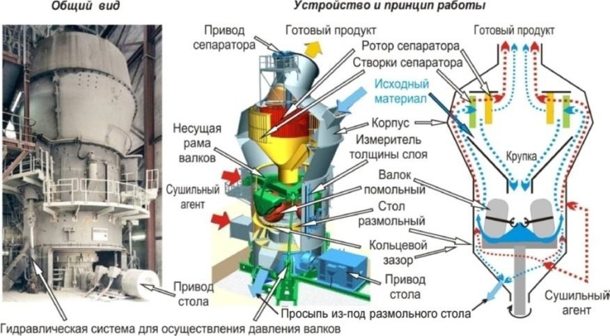
Figure 1 – Disc-roller mill
The poppet-roller mill consists of a housing, a rotating grinding table – a poppet, a supporting frame with grinding rolls, hydraulic system and separator (Fig.1). The rolls are located on a special frame, moved in the vertical direction, and pressed by the hydraulic system to the crushed material with pressure close to 100 atmospheres, which is on the grinding table
The initial solid material is fed to the grinding table, under the action of centrifugal force falls under the rolls, is crushed, worn and moved to the edge of the container, where it is picked up by the flow of gases, which is created by a mill smoke pump and moves to a separator built into the mill. Large the fraction from the separator is returned for additional grinding, and the finished product, together with the drying agent (hot gases), is sent to the bag filter and cyclones. The drying agent (hot gases) is produced by in the generator of hot gases and is fed under the grinding table, after which it enters the mill through a gap between the container and the case. The productivity of the disc-roll mill is regulated depending on the difference in the dilution before and after the grinding table, i.e. by the resistance to the dust and gas flow, arising in the annular gap between the mill body and the plate. As you know, this resistance depends on the concentration of the material in the dust and gas flow. Therefore, when the pressure increases above the norm the feed of feedstock to the mill is reduced, and, conversely, with a decrease in pressure, it is necessary to increase feed of feedstock
According to the set temperature of the dust and gas flow at the outlet of the disc-roll mill, which corresponds to the required humidity of the material, the temperature of the hot gases at the entrance to the mill is regulated by changes in the flow rate of natural gas supplied to the burner of the hot gas generator
Hot gas generators are used in combination with various technological equipment: mills various types; drum drying plants; apparatus and installations for drying or burning in a fluidized bed, etc. For hot gas generators, various types of fuels can be used: gases (natural, coke, biogas, synthetic, blast furnace, petroleum); liquid fuel (diesel, fuel oil); brown coal and wood dust
Figure 2 shows an enlarged technological scheme for the use of a hot gas generator in the technology of grinding solid material on the basis of a disc-roll mill considered above
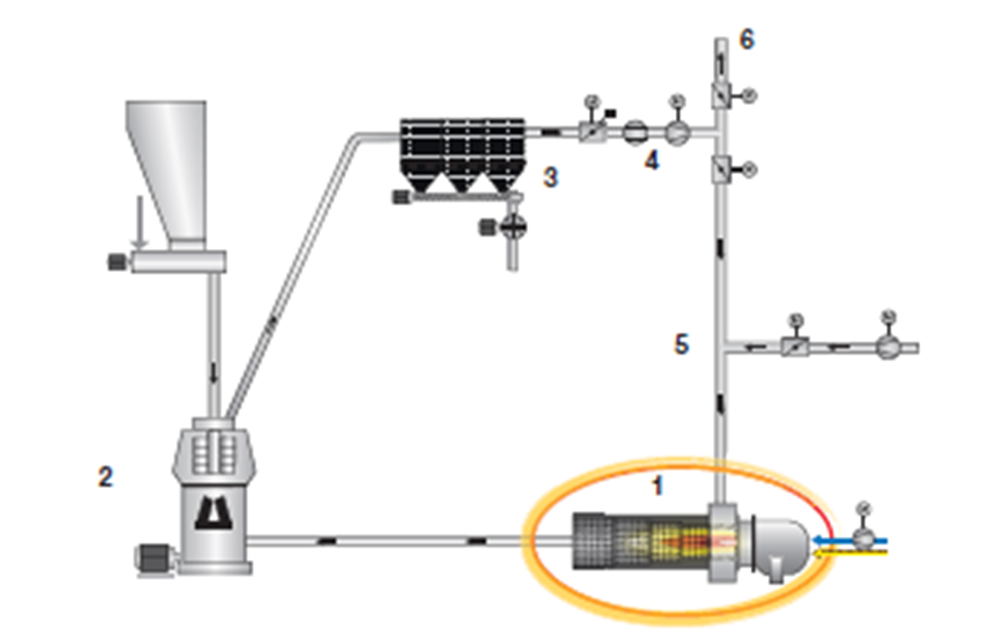
Figure 2 – Application of a hot gas generator for a disc-roll mill
The hot gas generator 1 carries out continuous production of a drying agent – hot gas for the process of grinding the material in a disc-roll mill 2 (Fig.2). Spent hot gases they are passed through the filter block 3 due to the thrust generated by the fan 4. Some of these purified gases leave the installation through the chimney 6, the other part returns back as recirculating and is supplied to the hot gas generator. Recirculating gases enter the hot gas generator through its supply spiral casing, they are fed through the perforated shell of the combustion chamber for cooling of metal parts and mixed with combustion products coming from the generator burner hot gases
Figure 3 shows a diagram of a hot gas generator, which is considered in this paper as the control object. Process gases or recirculating gases are fed into the generator. gases are passed through the spiral casing 2 and cooled as a result of the action of the directional flow of the casing 3 and the perforated inner shell 4 (Fig.3). Recirculating gases enter the combustion chamber through the annular slots 5 and holes in the perforated shell. Here they mix with hot gases from the burning of the gorenje 1
The operation of the hot gas generator is based on mixing process gas – recirculating gas with gorenje products – natural gas to obtain the desired volume of gas–air mixture - hot gases with the required temperature and flow rate. The heat output of the burner, and, accordingly, the temperature hot gases can be regulated by changing the supplied amount (flow rate) of natural gas and the corresponding change in the flow rate of air supplied to the burner for gorenje. Recirculating gases for the mixes are fed through a spiral casing into the mixing chamber of the hot gas generator housing, where the combustion products of the burner are mixed with recirculating gases. By adjusting the thermal the burner power and the amount of recirculating gases supplied for mixing can achieve the required temperature and the required volume of hot gases at the generator output
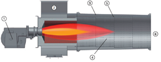
Figure 3 – Hot gas generator device
For efficient and complete combustion of fuel in the burner, it is necessary to maintain an optimal ratio between the flow rate of natural gas and the flow rate of air, which is provided by the change in air flow, hot gas generator supplied to the burner
Taking into account the above, the controlled variables of the hot gas generator are: the temperature of the hot gases at the output of the generator tGG; the flow rate of hot gases at the output of the generator GGG
The control actions are: the consumption of natural gas GPG and the consumption of air GV supplied to the burner hot gas generator; flow rate of recirculating gas GRG supplied to the mixing chamber of the generator hot gases
Disturbing influences are: natural gas temperature tPG; air temperature tB; temperature recirculating gas tRG; the recirculating gas flow rate GRG has a disturbing effect on the temperature of hot gases tGG; natural gas consumption GPG and air consumption GB, have a disturbing effect on the flow of hot gases GGG
Thus, a scheme of material flows and information variables of the hot gas generator is obtained (Fig.4), as well as a scheme of representation of the hot gas generator as a control object (Fig.5)
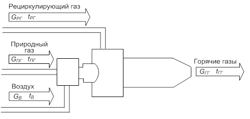
Figure 4 – Flow diagram of the hot gas generator
The main input material flows of the hot gas generator (Fig.4) are natural gas and air entering the burner and recirculating gas entering the mixing chamber of the generator
The input material flow is natural gas supplied to the burner of the hot gas generator, It is characterized by such information variables as the GPG flow rate and the TPG temperature (Fig.4). The GPG natural gas flow affects both controlled variables: the control one affects the temperature hot gases tGG and disturbing – on the flow of hot gases at the output of the generator GGG (Fig.5). Temperature natural gas tPG has a disturbing effect on the temperature of hot gases tPG (Fig.5)
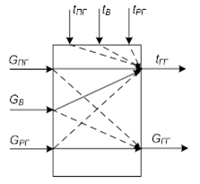
Figure 5 – Diagram of a hot gas generator as a control object
The input material flow – air supplied to the burner of the hot gas generator, is characterized by information variables such as flow rate GB and temperature tB (Fig.4). Air flow GB has effects on both controlled variables: control – on the temperature of hot gases tGG and disturbing – the flow rate of hot gases at the output of the generator GGG (Fig.5). The air temperature tV has a disturbing the effect on the temperature of hot gases tGG (Fig.5)
<The input material flow – the recirculating gas supplied to the mixing chamber is characterized by the following information variables, such as the flow rate GG and temperature TG (Fig.4). The flow rate of the recirculating gas GG it affects both controlled variables: the control one affects the flow of hot gases at the outlet the generator GGG and the disturbing influence on the temperature of hot gases tGG (Fig.5). The temperature of the recirculating gas tRG has a disturbing effect on the temperature of hot gases tGG (Fig.5)
The output material flow is hot gas, at the output of the hot gas generator, is characterized by the following information variables, such as flow GGG and temperature tGG (Fig.4). Both information variables of this material flow, the flow rate GGG and the temperature tGG are controlled variables the control object under consideration is a hot gas generator (Fig.5)
The performed analysis shows that for use in the development of ACS by a hot gas generator the feedback principle is most suitable when it is implemented in the form of a multi-contour cascade structure ACS. Intermediate variables for which additional internal contours need to be implemented The controls are: natural gas flow GPG and air flow GB – for the hot gas temperature control circuit tGG; recirculating gas flow GG – for the flow control circuit hot gases GGG. Thus, a diagram of the concept of building a self-propelled gun by a hot gas generator of a disc-roll mill is obtained, which is shown in Fig.6
The ACS with the temperature of hot gases is a multi-circuit automatic control system, the setting effect for which is the temperature value of hot gases required by the technology at the output of the generator tGGZAD (Fig.6)
Internal control circuits for natural gas flow and air flow are necessary to reduce inertia and increase the accuracy of the temperature control process and consist of the following elements: internal natural gas flow control circuit – natural gas flow sensor DRP, regulator the flow rate of natural gas RRP and the control valve of natural gas RCP with an actuator (electric drive) M; internal air flow control circuit – air flow sensor DRV, the RRV air flow regulator and the RVV air control valve with an actuator (electric drive) M. The external control circuit for the temperature of hot gases forms a setting effect for internal circuits and consists of the following elements: hot gas temperature sensor DTG and RT temperature controller (fig.6)
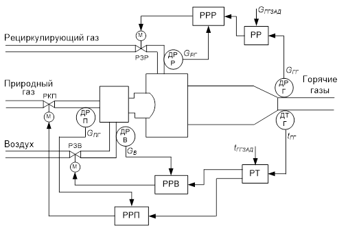
Figure 6 – Diagram of the concept of building an ACS with a hot gas generator
The ACS hot gas flow rate is a two-circuit automatic control system, the setting effect for which is the required technology value of the flow rate of hot gases at the outlet generator GGGZAD (fig.6). The internal control circuit of the recirculating gas flow is necessary for reducing inertia and improving the accuracy of the hot gas flow control process and consists of the following elements: recirculating gas flow sensor DRR, recirculating gas flow regulator PPR and the control valve of the recirculating gas RZR with an actuator (electric drive) M. The external hot gas flow control circuit generates a setting effect on the recirculating gas flow rate for the internal circuit and consists of the following elements: hot gas flow sensor gas DRG and hot gas flow regulator PP
Conclusions
Thus, the article analyzes the hot gas generator of a disc-roll mill as an object automatic control, on the basis of which the formalization of the object in question is carried out, controlled variables, controlling and disturbing effects are determined. It is shown that in order to achieve the required quality of control, it is necessary to use the feedback principle and its development – multi- circuit subordinate control. A cascade multi-contour structure of the ACS has been developed. hot gases, with internal control circuits for natural gas flow and air flow, external the hot gas temperature control circuit. To achieve the required quality of flow control at the output of the generator, a two-circuit structure of the ACS with a hot gas flow is proposed, with an internal control circuit for the flow of recirculating gases and an external flow control circuit hot gases
List of sources
- Борщев, В.Я. Оборудование для измельчения материалов: дробилки и мельницы. Учебное пособие. / В.Я. Борщев. – Тамбов: Издательство Тамбовского Технического Университета, 2004. – 75с.
- Бауман, В.А. Механическое оборудование предприятий строительных материалов, изделий и конструкций / В.А. Бауман, Б.В. Клушанцев, В.Д. Мартынов – М.: Машиностроение. – 1980 – 324 с.
- Фокин, В.М. Теплогенерирующие установки систем теплоснабжения. / В.М. Фокин. – М.: «Издательство Машиностроение-1», 2006, – 240 с.
- Теплоэнергетика и теплотехника: Общие вопросы. Справочник. Под общ. ред. В.А. Григорьева и В.М. Зорина. – М.: Энергия, 1980. – 528 с.
- Лукас, В. А. Теория управления техническими системами. Учебный курс для вузов. / В.А. Лукас – Третье издание, переработанное и дополненное – Екатеринбург, Изд-во УГГГА, 2002. – 675 с.
- Уваров, В.А. Процессы в производстве строительных материалов и изделий: учеб. пособие / В.А. Уваров, И.А. Семикопенко, Г.И. Чемеричко. – Белгород: Изд-во БГТУ им. В.Г. Шухова, 2002. – 121 с.
- Клюев, А.С. Наладка средств автоматизации и автоматических систем регулирования: Справочное пособие. / А.С. Клюев, А.Т. Лебедев, С.А. Клюев, А.Г. Товарнов; — 2-е изд., перераб. и доп. - М.: Энергоатомиздат, 1989. - 368 с.
- Фокин, В.М. Тепловой расчет теплогенератора: Учебное пособие. / В.М. Фокин. – Волгоград, 2000. – 68 с.
- Шувалов С.И., д-р техн. наук, Михеев П.Г., Веренин А.А., Асташов Н.С. Математическая модель шаровой барабанной мельницы для анализа работы сепаратора пыли: статья / «Вестник ИГЭУ» Вып.3 - 2009 г
- Романович А.А. Исследование процесса помола материалов предварительно измельченных в пресс-валковом измельчителе статья / Вестник БГТУ им. В.Г. Шухова 2015, №5